


Control Cavity 9–1
Chapter 9 — Control Cavity
Removing the Control Housing
1.
Remove the top housing and level sensors as described in
Chapter 7 – Top Housing
and
Chapter 8 – Level Sensor
, respectively.
2.
Loosen and remove the air release plug using a 3/16-inch hex key.
3.
Install the control cavity air test fitting and use a regulated low pressure line or hand
pump to pressurize the control cavity to 5 psi.
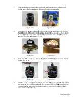
4.
Use soapy water to test for leaks around the O-ring joint and compression nut.
Submerging the assembly may aid with finding leaks. Clearing trapped air may take
several minutes.
5.
Use a 1/2-inch deep-well socket and a 1/2-inch wrench to remove the three retaining
bolts from the control housing.
6.
Break the seal and lift the control housing using two pry bars. Pry upward until the
control housing is free, taking caution not to pull the wires apart from the control
bracket assembly.
Figure 9-1
Figure 9-2
Содержание Extreme Series
Страница 1: ...Service Manual E One Extreme Grinder Pumps 240V 60 Hz Hardwired Controls...
Страница 2: ......
Страница 32: ...Pump End 5 8 Figure 5 9a D Series Pump Exploded View...
Страница 33: ...Pump End 5 9 Figure 5 9b W Series Pump Exploded View...
Страница 34: ...Pump End 5 10 Figure 5 9c Gatorgrinder GH Series Pump Exploded View...
Страница 35: ...Pump End 5 11 Figure 5 9d IH091 Pump Exploded View...
Страница 36: ...Pump End 5 12...
Страница 58: ...Level Sensor 8 10 Figure 8 35 Level Sensor Assembly Exploded View all hardwired pumps...
Страница 70: ...Mechanical Seal Assembly 11 2...
Страница 75: ......


