Troubleshooting 2–11
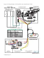
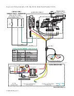
Figure 2-3a, Wiring Schematic, 240V, May 2015 & Later (Serial Number 531884)
CAPACITOR
BLEED
RESISTOR
MOTOR
COMPARTMENT
START
GRN-G
MAIN
MAIN
1
3
2
1
3
YEL
ORN
GRAY
RED
BLU
PROTECTOR
PROTECTOR
THERMAL
THERMAL
SWITCH
SMART
BLK
CONTROL COMPARTMENT
MOTOR section
CONTROL COMPARTMENT
COVER section
1
3
2
(ALARM)
SWITCH
2
1
3
(ON-OFF)
SWITCH
TO MOTOR
GROUND
2
4
6
14
A2
T1
T2
T3
NO
A1
13
5
3
1
NO
I3
L2
L1
MOTOR CONTACTOR
GRINDER PUMP CORE
Level Control Compartment
Tray Cable
BRN-L1 Control
RED-L1
EQD
Pin #
Wire Color
Function
1
Brown
Manual Run
2
Red
L1
3
Black
L2
4
Ground
5
Yellow
Alarm Power Feed
6
Blue
Alarm Power Return
Green w/ Yellow Stripe
240VAC
NEUTRAL
L2
L1
AMP
30
MAIN SUPPLY PANEL
N
G
240VAC 60Hz
TWO POLE - HARDWIRE
(RECOMMENDED WIRING CONFIG,
NOT SUPPLIED BY E/ONE)
HARD WIRE OPTION
Alarm Yellow and Blue wires go to the alarm panel only
Motor Control Red and Brown wires go to both alarm panel and motor contactor
ALARM/DISCONNECT
GROUND
PUMP
BREAKER
15
15
ALARM
BREAKER
L1
L2
ALARM LAMP
REDUNDANT
RUN
COIL
COM
N.O.
N.C.
Basic Alarm
Board
(PC1139G01)
SILENCE
RELAY
COIL
COM
N.O.
N.C.
PTC
RESIST
OR
AUT
O-RESET
FUSE
Resistor
LED
GREEN
RUN
SER
VICE
NEUTRAL
MANUAL
RUN
ALARM
FEED
ALARM
RETURN
BUZZER
SILENCE
SWITCH
MANUAL
RUN
SW
.
Resistor
PUMP
L2
ALARM
L1
WIRED
WIRELESS
LEVEL CONTROL
Using the EXTREME color Scheme
NA0035P11 REV. B
BLK-L2
Содержание Extreme Series
Страница 1: ...Service Manual E One Extreme Grinder Pumps 240V 60 Hz Hardwired Controls...
Страница 2: ......
Страница 32: ...Pump End 5 8 Figure 5 9a D Series Pump Exploded View...
Страница 33: ...Pump End 5 9 Figure 5 9b W Series Pump Exploded View...
Страница 34: ...Pump End 5 10 Figure 5 9c Gatorgrinder GH Series Pump Exploded View...
Страница 35: ...Pump End 5 11 Figure 5 9d IH091 Pump Exploded View...
Страница 36: ...Pump End 5 12...
Страница 58: ...Level Sensor 8 10 Figure 8 35 Level Sensor Assembly Exploded View all hardwired pumps...
Страница 70: ...Mechanical Seal Assembly 11 2...
Страница 75: ......


