Pump End 5–6
Removing the Pump Rotor
1.
Support the end of the motor shaft with a wooden block.
2.
Use a hammer and a 1/8-inch punch to remove the groove pin that retains the pump
rotor.
3.
Slide the rotor off of the shaft. If the rotor sticks, use a plastic mallet to tap the end of
the rotor until it comes off. Take care not to bend the armature shaft.
Note:
Do not disturb the mechanical seal. String-like fibers and other debris around the seal are
normal. If the seal bellows is moved on the shaft, it will create a leak path and flood the
motor cavity. The mechanical seal should only be replaced at a repair shop and only during
a total overhaul of the pump motor.
Assembling the Pump/Grinder Mechanism
1.
If the rotor was removed, slide the rotor over the armature shaft, compressing the
seal spring. The spring washer may need to be aligned with the shoulder of the
armature shaft. Press the groove pin into place with channel lock pliers. Lubricating
the groove pin will help to ease the installation. Do not use a hammer to beat in
groove pin; doing so may bend the armature shaft.
2.
Install the new pump stator and liner over the rotor. The rotor or internal bore of the
stator should be lubricated with a small amount of silicone grease; most new stators
are lubricated at the factory. Ensure the lip of the stator is uniformly seated in the
motor head groove.
3.
If not already done, remove the old pump liner from suction housing.
4.
Install the suction housing. Tighten the bolts diagonally to maintain housing
alignment with the armature shaft. Failure to align properly will cause the cutter
wheel to hit the shredder ring.
5.
Apply a small amount of Anti-Seize to the threads of the armature shaft and hand-
tighten the cutter wheel onto the shaft. Do not overtighten the cutter wheel; it will be
difficult to remove the next time the unit is serviced.
6.
Seat the shredder ring in the suction housing, ensuring that the four notched ears
are properly aligned with the four threaded holes. Set with a rubber mallet or hammer
and a block of wood. Do not strike the shredder ring with a steel hammer. Start with
Figure 5-8
Содержание Extreme Series
Страница 1: ...Service Manual E One Extreme Grinder Pumps 240V 60 Hz Hardwired Controls...
Страница 2: ......
Страница 32: ...Pump End 5 8 Figure 5 9a D Series Pump Exploded View...
Страница 33: ...Pump End 5 9 Figure 5 9b W Series Pump Exploded View...
Страница 34: ...Pump End 5 10 Figure 5 9c Gatorgrinder GH Series Pump Exploded View...
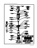
Страница 35: ...Pump End 5 11 Figure 5 9d IH091 Pump Exploded View...
Страница 36: ...Pump End 5 12...
Страница 58: ...Level Sensor 8 10 Figure 8 35 Level Sensor Assembly Exploded View all hardwired pumps...
Страница 70: ...Mechanical Seal Assembly 11 2...
Страница 75: ......


