Motor Cavity 10–4
Note:
If you are applying Loctite 641 to the bearing race, apply it to the portion of the race that
will enter the bearing bore first. If you are applying Loctite 641 to the bearing bore, apply it
to the area of the bore that will come into contact with the bearing race first when it is being
installed (Figure 10-8).
5.
Install the armature assembly into the motor head.
6.
With the motor housing upside down on the bench, place the spring washer into the
top bearing bore. Lift the motor head/armature assembly by the motor head. Grasp
the armature shaft below the motor head and turn it upside down. Carefully slide the
assembly into the motor housing, ensuring that the discharge elbow is aligned on the
appropriate side. Tighten the bolts and four new locknuts evenly in a cross pattern to
140 inlb.
7.
Assemble the mechanical seal as described in
Chapter 11 – Mechanical Seal
Assembly
.
8.
Perform motor cavity air tests as described in
Chapter 12 – Final Tests Procedures
.
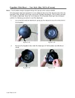
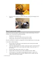
Figure 10-10
Figure 10-9
Содержание Extreme Series
Страница 1: ...Service Manual E One Extreme Grinder Pumps 240V 60 Hz Hardwired Controls...
Страница 2: ......
Страница 32: ...Pump End 5 8 Figure 5 9a D Series Pump Exploded View...
Страница 33: ...Pump End 5 9 Figure 5 9b W Series Pump Exploded View...
Страница 34: ...Pump End 5 10 Figure 5 9c Gatorgrinder GH Series Pump Exploded View...
Страница 35: ...Pump End 5 11 Figure 5 9d IH091 Pump Exploded View...
Страница 36: ...Pump End 5 12...
Страница 58: ...Level Sensor 8 10 Figure 8 35 Level Sensor Assembly Exploded View all hardwired pumps...
Страница 70: ...Mechanical Seal Assembly 11 2...
Страница 75: ......


