


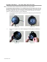


Top Housing 7–6
9.
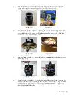
Install and secure the four top housing bolts with four new Nyloc nuts and tighten in
an X pattern.
10.
Install the four bolts and secure the check valve/anti-siphon to the discharge elbow.
11.
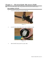
Reconnect the power cable to the alarm panel.
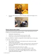
12.
Re-install the Equalizer.
13.
Secure the Equalizer tube to the power cable with the retaining clips.
Cable Replacement
Cable Removal
1.
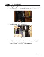
Remove top housing, following the appropriate instructions for top housing removal
and replacement above.
2.
Remove the level sensor as described in
Chapter 8 – Level Sensor
.
3.
Remove the split ring compression nut from the control housing.
4.
Remove the control housing as described in
Chapter 9 – Control Cavity
.
5.
Disassemble the level sensor as described in
Chapter 8 – Level Sensor
.
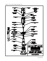
Figure 7-12
Содержание Extreme Series
Страница 1: ...Service Manual E One Extreme Grinder Pumps 240V 60 Hz Hardwired Controls...
Страница 2: ......
Страница 32: ...Pump End 5 8 Figure 5 9a D Series Pump Exploded View...
Страница 33: ...Pump End 5 9 Figure 5 9b W Series Pump Exploded View...
Страница 34: ...Pump End 5 10 Figure 5 9c Gatorgrinder GH Series Pump Exploded View...
Страница 35: ...Pump End 5 11 Figure 5 9d IH091 Pump Exploded View...
Страница 36: ...Pump End 5 12...
Страница 58: ...Level Sensor 8 10 Figure 8 35 Level Sensor Assembly Exploded View all hardwired pumps...
Страница 70: ...Mechanical Seal Assembly 11 2...
Страница 75: ......


