


Control Cavity 9–6
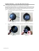
Control Bracket Installation — 240V
1.
Connect the cable ground wire to the chassis and connect the proper wires to the
start switch before installing the bracket.
2.
Refer to the wiring road map in
Chapter 2 – Troubleshooting
for the correct wiring
configuration.
Control Bracket Installation — 120V
1.
Connect the cable ground wire to the chassis and connect the proper wires to the
start switch before installing the bracket.
2.
Refer to the wiring road map in
Chapter 2 – Troubleshooting
for the correct wiring
configuration.
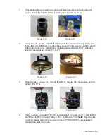
Control Housing Installation
1.
Unhook the control housing from the motor housing.
2.
Slide the control housing back onto the motor housing, making sure not to pinch or
crimp any of the wires. The air release plug must be removed in order to install the
control housing onto the motor housing.
3.
Reinstall the three bolts and use three new Nyloc nuts to secure the control housing.
4.
Perform the control cavity leak test as described in
Chapter 12 – Final Test
Procedures
.
5.
Apply Loctite 598 generously to the threads of the air release plug and install
it. Apply Loctite 598 over the plug after it is installed; apply more Loctite 598 if
necessary to cover the plug.
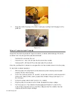
6.
Reinstall the top housing as described in
Chapter 7 – Top Housing
.
Figure 9-5
Figure 9-6
Содержание Extreme Series
Страница 1: ...Service Manual E One Extreme Grinder Pumps 240V 60 Hz Hardwired Controls...
Страница 2: ......
Страница 32: ...Pump End 5 8 Figure 5 9a D Series Pump Exploded View...
Страница 33: ...Pump End 5 9 Figure 5 9b W Series Pump Exploded View...
Страница 34: ...Pump End 5 10 Figure 5 9c Gatorgrinder GH Series Pump Exploded View...
Страница 35: ...Pump End 5 11 Figure 5 9d IH091 Pump Exploded View...
Страница 36: ...Pump End 5 12...
Страница 58: ...Level Sensor 8 10 Figure 8 35 Level Sensor Assembly Exploded View all hardwired pumps...
Страница 70: ...Mechanical Seal Assembly 11 2...
Страница 75: ......


