


A-4
DL600E E1 Data Multiplexer UserÕs Guide
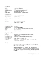
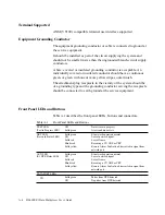
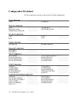
Terminal Supported
ANSI (VT100) compatible terminal user interface supported
Equipment Grounding Conductor
The equipment grounding conductor or cable is connected to ground at
the service equipment.
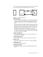
It should be installed as part of the circuit supplying the system and
should not be smaller in size than the ungrounded branch-circuit supply
conductors.
A bare, covered or insulated grounding conductor is acceptable. An
individually covered or insulated conductor should have a continuous
green, or green with one or more yellow stripes, outer Þnish.
The attachment-plug receptacle in the vicinity of the system should be
of a grounding type and the grounding conductor serving the receptacle
should be connected to earth ground at the service equipment.
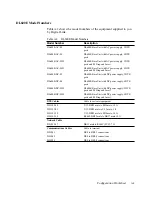
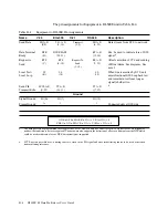
Front Panel LEDs and Buttons
Table
A-1
describes the front panel LEDs, buttons and connectors.
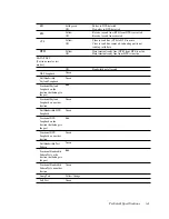
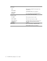
Table A-1
Front Panel LEDs and Buttons
TEST LED
(Test in Progress LED)
Off
Solid green
No tests are in progress
A test condition exists
NET LED
(Network Status LED)
Solid green
Off
Solid red
Blinks red
Solid yellow
E1 network operation normal
Loss of network signal
Loss of frame
Receiving a CV, OOF or CRC
Remote Alarm Indication
bit asserted in signal from
network port
AUX LED
(E1 DTE Status LED)
Solid green
Off
Solid red
Blinks red
Solid yellow
E1 network operation normal
Loss of network signal
Loss of frame
Receiving a CV, OOF or CRC
Remote Alarm Indication
bit asserted in signal from
network port
DATA PORT LEDs
TD
Solid green
Off
Pulses from DTE detected
No pulses from DTE detected
Содержание DL600E
Страница 1: ...DL600EE1 DataMultiplexer User s Guide...
Страница 2: ......
Страница 12: ...xiv DL600E E1 Data Multiplexer User s Guide...
Страница 14: ...xvi DL600E E1 Data Multiplexer User s Guide...
Страница 20: ...xxii DL600E E1 Data Multiplexer User s Guide...
Страница 26: ...1 6 DL600E E1 Data Multiplexer User s Guide...
Страница 34: ...2 8 DL600E E1 Data Multiplexer User s Guide...
Страница 102: ...5 26 DL600E E1 Data Multiplexer User s Guide...
Страница 113: ...Appendix A DL600E Technical Speci cations...
Страница 122: ...A 10 DL600E E1 Data Multiplexer User s Guide...
Страница 123: ...Appendix B Connector and Pin Assignments...
Страница 132: ...B 10 DL600E E1 Data Multiplexer User s Guide...
Страница 144: ...G 12 DL600E E1 Data Multiplexer User s Guide...