7
PRO-VISION rev.04
PRO-VISION
Do not install rigid conduit into electrical
knockouts. Only nylon cable glands are
permitted for cable or wire fastening.
The controller has no power-on switch.
An external switch or circuit breaker
shall be included in the building instal-
lation to interrupt power to L and N
electric power lines. It shall be in close
proximity to the equipment and within
easy reach of the operator. It shall be
marked as the disconnecting device for
the equipment.
Alarm Connection
2.2.2.
There are two types of alarms on the market.
One type activates when current is cut off at its
input; the other type of alarm activates when
current is supplied at its input. For an alarm of
the first type, use the NC terminal as shown on
the wiring diagram. For an alarm of the second
type, use the NO terminal.
2.2.3. Sensor Inputs
Sensors operate at low voltage and are
isolated from the supply. Make sure that
sensor cables remain isolated from all high
voltage sources. In particular, do not route
the sensor cables through the same electri-
cal knockout as other cables. Do not connect
the shield from the sensor cable to a terminal
or a ground.
Extending a sensor:
Each sensor can be ex-
tended up to 500 feet (150 meters).
To extend a sensor: Use a shielded cable of
outside diameter between 0.245 and 0.260 in
(6.22 and 6.60 mm) (the cable dimensions
should not be under 18 AWG) to ensure the
cable entry is liquid tight.
Do not ground the
shielding.
It is preferable to solder the cable joint to
ensure a proper contact between the two
cables.
1
4
7
DEL
2
5
8
0
3
6
9
+/-
AM/PM
ENTER
BACK
Main Menu
Current conditions
Set Point
Minimum ventilation
On/Off Settings
Inlets/Vents
Start flock / Egg
Light Programs
Alarms
History
Set-up
MAIN
MENU
Menu
Selectors
Graphic
LCD
Display
Alarm
Status
LED
Home
Key
Back
button
Arrow keys
(Right = Page-Down
Left = Page-Up)
Adjustment
Buttons
Digital Keypad
+/-
AM/PM
Button
Delete
Do not run sensor cables next to other
power cables. When crossing over other
cables, cross at 90°.
Defective sensors:
An alarm is generated
when a defective sensor is detected. Defec-
tive sensors are identified in the
“Alarm”
menu. Refer to chapter 13 for further
information on the alarms.
2.2.4. 0-10V Output Connection
It is recommended to use a 18 to 22 AWG
wire to connect the devices to the 0-10V
outputs. This type of output can be used to
connect various devices such as lights.
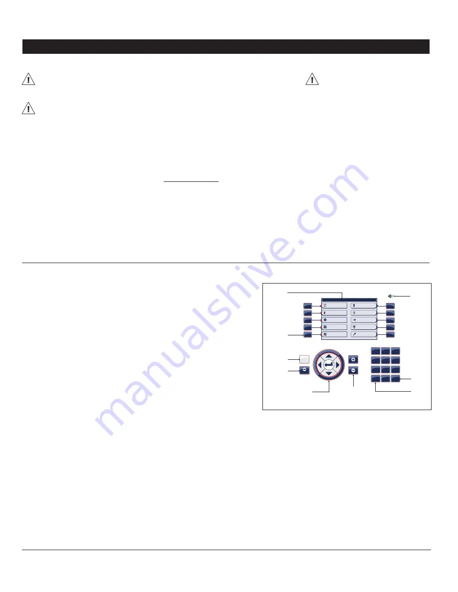
3. USER INTERFACE
3.1. Location of the Controls
Graphic LCD display —
The large graphic
LCD screen is used to display the parameters
and menus.
Menu selectors —
The menu selectors allow
selecting a tab on screen.
Home key —
This short-cut key provides ac-
cess to the main menu.
Back —
The
“Back”
key is used to go back to
the previous menu.
Arrow keys —
The arrow keys allow select-
ing a parameter on screen. The right and
left arrow keys can also be used to move
through the display by pages (left=page-up,
right=page-down).
Enter —
The
“Enter”
key is used to change
the value of non-numerical parameters.
Pressing this key makes a drop-down choice
menu appear.
Adjustment buttons —
The adjustment but-
tons allow increasing or decreasing the value
of a parameter.
Delete —
The delete key allows
clearing the last digit that has
been posted while editing a
numerical value.
+/- & AM/PM button —
This
push-button allows entering
a negative value and allows
changing the AM/PM time in-
dicator.
Digital keypad —
The digital key-
pad is used to modify the value
of numerical parameters.
Alarm Status LED —
The alarm
LED turns red when an alarm
situation is active or turns green
when there is no alarm.
3.2. Adjusting a Parameter
When a parameter is selected, the control-
ler gives indications about the way it can
be modified at the bottom of the screen. A
parameter can either be modified with the
adjustment buttons, with the digital keypad or
by pressing the
“Enter”
key and then selecting
an item from a drop-down menu. Follow the
instructions on screen to modify the value
of a parameter.
Содержание PRO-VISION
Страница 54: ...PRO VISION NOTES NOTAS...
Страница 55: ...PRO VISION NOTES NOTAS...


