42
PRO-VISION rev.04
PRO-VISION
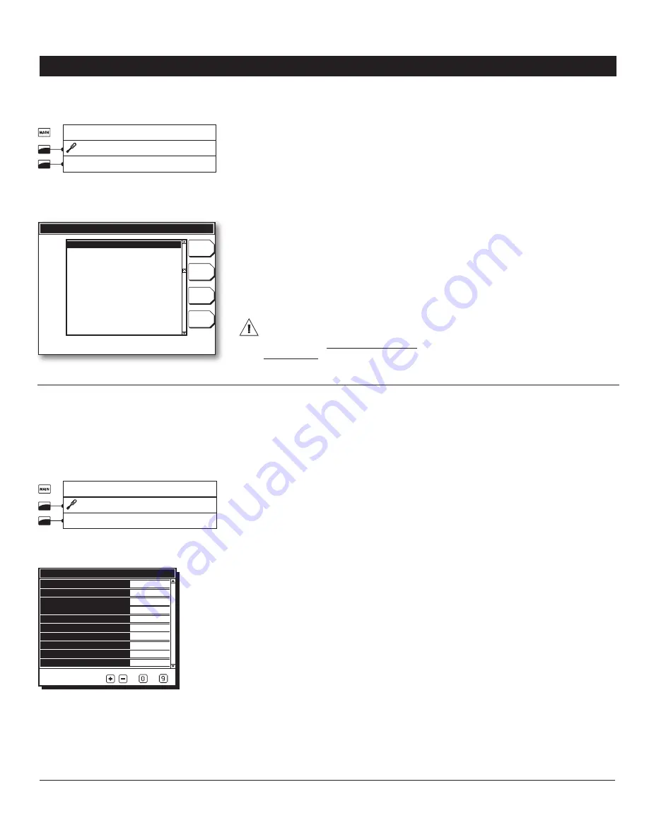
Select:
1.
Main menu
* Set-up
Update
* A complete-access password may be required to
access this menu (see section 4.2.1).
Update
Soft
Update
all
Update
Settings
Save all
Select file to install
Update
PRO-VISION~1.pkg
PRO-VISION~2.pkg
PRO-VISION~3.pkg
Making a backup:
2.
Press the
“Save All”
tab in order to save your
PRO-VISION software and parameter set-
tings on the USB card. Each time you make a
backup of your control, the controller creates
a new PRO-VISION~X.pkg file at the root of
the memory card. If this file name already
exists, it will be saved under a different
name (“PRO-VISION~1.pkg” for instance).
This way, the controller will never erase a
file on the card.
Loading new settings and/or software:
3.
In order to load a new software and/or param-
eter settings, select the desired configuration
file from the scrolling list and then select the
proper
“Update”
tab with the menu selector.
Here are the different possibilities:
The PRO-VISION can only read the
files located at the root of the USB
memory card. It cannot access any
sub-directory!
16. DIAGNOSTIC
The diagnostic menu allows testing the con-
troller’s hardware.
Select:
1.
Main menu
* Set-up
Diagnostic.
* A complete-access password may be required to
access this menu (see section 4.2.1).
Diagnostic
Activate LED
Activate LCD Test
Activate Alarm relay
Activate output relay
Activate 0-10V test
0-10V 1 output value
0-10V 1 output reading
0-10V 2 output value
0-10V 2 output reading
Communication in use x%
No
No
No
No
No
No
No
No
No
80%
To modify use
-
Activate the desired hardware test:
2.
Update soft —
Press this tab in order to load
the software of the selected file into your
PRO-VISION controller. This will affect the
software of the controller without affecting
your parameter settings.
Update settings —
Press this tab in order to
load the parameter settings of the selected
file into your PRO-VISION controller. This
transfer will affect the parameter settings
of the controller without affecting the soft-
ware.
Update all —
Press this tab in order to load the
software & parameter settings of the selected
file into your PRO-VISION controller. This will
affect the software and parameter settings
of the controller.
Once the transfer is over the controller
4.
automatically reboots itself.
You can now remove the USB card from
5.
the connector.
Activate LED —
Use this function to test both
colors of the alarm LED.
Activate LCD Test —
Use this function to test
the LCD screen.
Activate Alarm relay —
Use this function to
test the alarm relay.
Activate output relay —
Type in the relay
number associated with the output you want
to test or type “0” to end this test.
Activate 0-10V test —
Select
“Yes”
to enable
the 0-10V test.
0-10V #x output value —
Assign the desired
voltage to the 0-10V output. The actual 0-10V
reading is displayed below. If the assigned
value does not match the output reading,
make sure there is no electrical noise on the
output and make sure that the load connected
to the output does not exceed the allowable
range (30 mA max). *
This parameter is accessible
if the 0-10V test is enabled above.
0-10V #x output reading —
This is the actual
voltage reading of the 0-10V output. It cannot
be modified.
Communication in use x% —
This is the
communication rate currently being used by
your controller. If this value gets higher than
100%, the reaction time of your controller is
likely to slow down. In order to decrease the
communication rate, you can either remove
some current sensors from the relay panels
or switch to the high-speed communication
mode (on condition that your application
exclusively uses relay panels with the
“CS”
technology). *
Refer to section 4.4 to change the
communication speed.
Содержание PRO-VISION
Страница 54: ...PRO VISION NOTES NOTAS...
Страница 55: ...PRO VISION NOTES NOTAS...


