background image


14-113

Cisco ASR 1000 Series Aggregation Services Routers Hardware Installation Guide

OL-13208-11

Chapter 14      Removing and Replacing FRUs from the Cisco ASR 1000 Series Routers

Removing and Replacing the Cisco ASR 1001 Router Power Supplies

Step 10

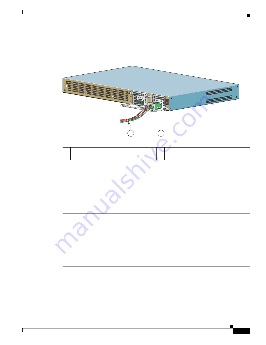
Use a tie wrap to secure the wires to the rack, so that the wires are not pulled from the terminal block 
plug by casual contact. Make sure the tie wrap allows for some slack in the ground wire as shown in 

Figure 14-87

.

Figure 14-87

Complete DC Terminal Block Plug Insertion and Secure Tie Wrap

Step 11

Make certain the terminal block plug is fully seated in the terminal block header on the DC power supply 
panel. You will hear a snap or click when installed properly.

Step 12

Remove the tape (if any) from the circuit-breaker switch handle and move the circuit-breaker switch 
handle to the on position.

Step 13

On the rear of the router, place the power supply Standby switch in the on position (O) to turn on the 
router.

The power supply LEDs light when power is supplied to the router.

This completes the procedure for connecting the DC power supply in the Cisco ASR 1001 Router.

Removing DC Input Power from the Cisco ASR 1001 Router

This section describes how to remove a DC power supply from the Cisco ASR 1001 Router. Follow these 
steps:

Step 1

Turn off the circuit breaker.

Step 2

On the rear of the chassis, place the Standby switch in the Standby position (|).

Step 3

Pull the terminal block plug connector out of the terminal block head in the power supply.

Step 4

Unscrew the two power supply fasteners on the unit.

1

Lead wires secured with a tie wrap

2

DC power supply terminal block plug being 
inserted into terminal block header.

207701

1

2

Содержание ASR 1000 Series

Страница 1: ... 170 West Tasman Drive San Jose CA 95134 1706 USA http www cisco com Tel 408 526 4000 800 553 NETS 6387 Fax 408 527 0883 Cisco ASR 1000 Series Aggregation Services Routers Hardware Installation Guide June 8 2015 Text Part Number OL 13208 11 ...

Страница 2: ...rference by using one or more of the following measures Reorient or relocate the receiving antenna Increase the separation between the equipment and receiver Connect the equipment into an outlet on a circuit different from that to which the receiver is connected Consult the dealer or an experienced radio TV technician for help Modifications to this product not authorized by Cisco could void the FC...

Страница 3: ...Conventions page xxi Safety Warnings and Cautions page xxii Related Documentation page xxvii Obtaining Documentation and Submitting a Service Request page xxviii Document Revision History The Document Revision History table below records technical changes to this document Document Version Date Change Summary OL 13208 11 July 2013 Added information about Cisco ASR1000 ESP200 OL 13208 10 July 2012 A...

Страница 4: ...010 Added information about Cisco ASR 1000 Series Routers 40G products Cisco ASR 1013 Router Overview and Installation page 279 Cisco ASR 1000 ESP40 page 81 Cisco ASR 1000 Series SPA Interface Processor page 90 Supported ASR 1000 Hardware Components page 29 OL 13208 06 November 2009 Added information about the Cisco 24 VDC power supply in the Cisco ASR 1002 Router See the following sections Cisco ...

Страница 5: ...0 Series Aggregation Services Routers The users of this guide should Be familiar with electronic circuitry and wiring practices Have experience as electronic or electromechanical technicians Have experience in installing high end networking equipment Certain procedures described in this guide require a certified electrician Document Organization The following table describes the chapters and appen...

Страница 6: ...R 1002 router and how to install it Chapter 9 Cisco ASR 1002 F Router Overview and Installation This chapter describes the Cisco ASR 1002 F router and how to install it Chapter 10 Cisco ASR 1013 Router Overview and Installation This chapter describes the Cisco ASR 1013 router and how to install it Chapter 11 Cisco ASR 1001 Router Overview and Installation This chapter describes the Cisco ASR 1001 ...

Страница 7: ...itions Chapter and Appendix Description Convention Indication bold font Commands and keywords and user entered text appear in bold font italic font Document titles new or emphasized terms and arguments for which you supply values are in italic font Elements in square brackets are optional x y z Required alternative keywords are grouped in braces and separated by vertical bars x y z Optional altern...

Страница 8: ...ust te zijn van de bij elektrische schakelingen betrokken risico s en dient u op de hoogte te zijn van de standaard praktijken om ongelukken te voorkomen Gebruik het nummer van de verklaring onderaan de waarschuwing als u een vertaling van de waarschuwing die bij het apparaat wordt geleverd wilt raadplegen BEWAAR DEZE INSTRUCTIES Varoitus TÄRKEITÄ TURVALLISUUSOHJEITA Tämä varoitusmerkki merkitsee ...

Страница 9: ...et betyr fare Du er i en situasjon som kan føre til skade på person Før du begynner å arbeide med noe av utstyret må du være oppmerksom på farene forbundet med elektriske kretser og kjenne til standardprosedyrer for å forhindre ulykker Bruk nummeret i slutten av hver advarsel for å finne oversettelsen i de oversatte sikkerhetsadvarslene som fulgte med denne enheten TA VARE PÅ DISSE INSTRUKSJONENE ...

Страница 10: ...befinner dig i en situation som kan leda till personskada Innan du utför arbete på någon utrustning måste du vara medveten om farorna med elkretsar och känna till vanliga förfaranden för att förebygga olyckor Använd det nummer som finns i slutet av varje varning för att hitta dess översättning i de översatta säkerhetsvarningar som medföljer denna anordning SPARA DESSA ANVISNINGAR ...

Страница 11: ...ero da declaração fornecido ao final de cada aviso para localizar sua tradução nos avisos de segurança traduzidos que acompanham o dispositivo GUARDE ESTAS INSTRUÇÕES Advarsel VIGTIGE SIKKERHEDSANVISNINGER Dette advarselssymbol betyder fare Du befinder dig i en situation med risiko for legemesbeskadigelse Før du begynder arbejde på udstyr skal du være opmærksom på de involverede risici der er ved ...

Страница 12: ...xxvi Cisco ASR 1000 Series Aggregation Services Routers Hardware Installation Guide OL 13208 11 Preface ...

Страница 13: ...0 Series Routers and the Cisco IOS software running on it contain extensive features and functionality which are documented in the following resources All documentation related to the Cisco ASR 1000 Series Routers is listed in the online Cisco ASR 1000 Series Aggregation Services Routers Documentation Roadmap Information in this master index includes troubleshooting tools and documentation regulat...

Страница 14: ...ease installed on your Cisco hardware To check the minimum software requirements of Cisco IOS software with the hardware installed on your router Cisco maintains the Software Advisor tool on Cisco com This tool does not verify whether modules within a system are compatible but it does provide the minimum IOS requirements for individual hardware modules or components Note Access to this tool is lim...

Страница 15: ... Internet gateway Branch or regional office aggregation Remote access aggregation Service provider applications Intended as the low end service provider edge and broadband aggregation device with similar throughput High end customer premises equipment CPE for business quality Internet access Service provider leased line aggregation Provider edge PE and high end customer edge CE for Layer 2 VPN or ...

Страница 16: ...1000 ESPs The Cisco ASR 1013 Router is designed with two zones Zone 1 and Zone 0 for redundancy and superslot spacing The Cisco ASR 1013 router has four 40G slots and two 100G slots The Cisco ASR 1001 Router is a one rack unit chassis that offers a compact form factor router that satisfies customer demands such as low power consumption and decreased usage of rack space The Cisco ASR 1001 Router ha...

Страница 17: ... ASR1000 ESP5 Cisco ASR1000 ESP10 Cisco ASR1000 ESP20 Integrated Cisco ASR1002 ESP F Cisco ASR1000 ESP40 Cisco ASR1000 ESP100 Cisco ASR1000 ESP200 Note See Chapter 3 Cisco ASR 1000 Series Routers Embedded Services Processors for detailed information about Cisco ESPs Cisco ASR 1000 SPA Interface Processors SIPs Cisco ASR1000 SIP10 Cisco ASR1002 SIP10 F Cisco ASR1000 SIP 40 Note See Chapter 4 Cisco ...

Страница 18: ...ed port adapter operation The Cisco QuantumFlow Processor processing provides Architecture to address Cisco ASR 1000 Series router performance cost power and feature velocity Next Generation forwarding and queuing subsystems for Cisco routers to provide data path acceleration The Cisco ASR 1000 Series route processor system performs the following system management functions Sending and receiving r...

Страница 19: ...uter Cisco ASR 1006 Router Cisco ASR 1004 Router Cisco ASR 1002 Router and Cisco ASR 1002 F Router Cisco ASR 1001 Router Cisco ASR 1002 X Router ASR1000 ESP5 Not compatible Not compatible Not supported Supported Not applicable Not applicable ASR1000 ESP10 Not compatible Supported Supported Supported Not applicable Not applicable ASR1000 ESP20 Not supported Supported Supported Not compatible Not ap...

Страница 20: ...outer These two components must be upgraded to support Cisco IOS XE Release 3 1S on the Cisco ASR 1013 Router Cisco ASR 1000 Series Router Configurations The Cisco ASR 1000 Series Routers are available in different packaging configurations Some of the chassis configurations are modular with separate field replaceable units FRUs for the Cisco ASR 1000 Series Route Processors the Cisco ASR 1000 Seri...

Страница 21: ...for each chassis For the Cisco ASR 1006 Router the cable management brackets contain five independent cable management U features to provide cable dressing for each card module slot For SIPs these brackets work in tandem with SPA product feature cable management to allow installation and removal of adjacent cards without having to remove cables For the Cisco ASR 1004 Router the cable management br...

Страница 22: ... This section describes the slot numbering for the Cisco ASR 1000 Series Routers Cisco ASR 1000 Series SPA Interface Processor SIP subslots begin their numbering with 0 and have a horizontal orientation The SIP subslot numbering is indicated by a small numeric label beside the subslot on the faceplate Some commands allow you to display information about the SPA itself such as show idprom module an...

Страница 23: ...could never replace one shared port adapter with an identical one the MAC addresses would always be different Also each time a shared port adapter was replaced other devices on the network would have to update their data structures with the new address If the other devices did not update quickly enough the same MAC address could appear in more than one device at the same time Note Storing the MAC ...

Страница 24: ... which in turn notifies the forwarding engine control processor FECP and then performs the following steps Rapidly scans the midplane for configuration changes Initializes all newly inserted shared port adapters noting any removed interfaces and placing them in the administratively shutdown state Brings all previously configured interfaces on the shared port adapter back to the state they were in ...

Страница 25: ...cified threshold The system continues to operate but operator action is recommended to bring the system back to a normal state Critical An out of tolerance temperature or voltage condition exists The system continues to operate however the system is approaching shutdown Immediate operator action is required Shutdown The processor has detected a temperature condition that could result in physical d...

Страница 26: ... parameters exceed a threshold You can also retrieve and display environmental status reports with the following commands show environment all show version show inventory show platform show platform software status control processor show diag Parameters are measured and reporting functions are updated every 60 seconds A brief description of each of these commands follows Note The example outputs d...

Страница 27: ... PEM Vin P0 Normal 115 V AC Temp PEM P0 Normal 27 Celsius Temp FC P0 Fan Speed 65 26 Celsius Temp FM P1 Normal 24 Celsius Temp FC P1 Fan Speed 65 26 Celsius V1 VMA R0 Normal 1098 mV V1 VMB R0 Normal 3295 mV V1 VMC R0 Normal 2495 mV V1 VMD R0 Normal 1791 mV V1 VME R0 Normal 1499 mV V1 VMF R0 Normal 1201 mV V1 12v R0 Normal 11938 mV V1 VDD R0 Normal 3261 mV V1 GP1 R0 Normal 903 mV V1 GP2 R0 Normal 1...

Страница 28: ...bootflash 39004543K bytes of SATA hard disk at harddisk Configuration register is 0x0 Example 1 3 show inventory Command The show inventory command displays an extended report that includes the product inventory listing of all Cisco products installed in the networking device The following is sample output of the show inventory command Router show inventory NAME Chassis DESCR Cisco ASR1004 Chassis...

Страница 29: ...t of the show platform software status control processor command Router show platform software status control processor RP0 online statistics updated 4 seconds ago Load Average healthy 1 Min 0 00 status healthy under 5 00 5 Min 0 00 status healthy under 5 00 15 Min 0 00 status healthy under 5 00 Memory kb healthy Total 8133932 Used 1754156 21 status healthy under 90 Free 6379776 78 status healthy ...

Страница 30: ...atus healthy over 10 Committed 365840 69 status healthy under 90 Per core Statistics CPU0 CPU Utilization percentage of time spent User 1 80 System 2 50 Nice 0 00 Idle 95 59 IRQ 0 00 SIRQ 0 10 IOwait 0 00 Example 1 6 show diag Command The show diag slot R0 eeprom detail command displays the configuration hardware information including DRAM and Static RAM SRAM on line cards To display more details ...

Страница 31: ...ance an orderable PID may describe a packaging configuration for a product or a bundled group of products sold tested and shipped together Specific unique device identifier UDI benefits include the following Identifies Individual Cisco products in your networks PIDs and SNs for service and replaceable products VIDs for product version visibility Facilitates discovery of products subject to recall ...

Страница 32: ...dware products and cannot overwritten in error Operating and management systems discover the UDI through standard interfaces and display the UDI in standard outputs Standard interfaces include the IETF standard ENTITY MIB Note Go to the following URL for complete information on the product identification standard http www cisco com go udi Serial Number Label Location This section contains graphics...

Страница 33: ...ide OL 13208 11 Chapter 1 Cisco ASR 1000 Series Routers Hardware Overview Cisco Product Identification Standard Figure 1 1 shows the serial number location for the Cisco ASR 1006 Router Figure 1 1 Cisco ASR 1006 Router Serial Number Label Location 280157 781 00578 01 SN XXXNNNNXXXX ...

Страница 34: ...tion Guide OL 13208 11 Chapter 1 Cisco ASR 1000 Series Routers Hardware Overview Cisco Product Identification Standard Figure 1 2 shows the serial number label location for the Cisco ASR 1004 Router Figure 1 2 Cisco ASR 1004 Router Serial Number Label Location SN XXXNNNNXXXX ...

Страница 35: ... OL 13208 11 Chapter 1 Cisco ASR 1000 Series Routers Hardware Overview Cisco Product Identification Standard Figure 1 3 shows the serial number label location for the Cisco ASR 1002 Router Figure 1 3 Cisco ASR 1002 Router Serial Number Label Location 280158 781 00579 01 SN XXXNNNNXXXX ...

Страница 36: ...L 13208 11 Chapter 1 Cisco ASR 1000 Series Routers Hardware Overview Cisco Product Identification Standard Figure 1 4 shows the serial number label location for the Cisco ASR 1002 F Router Figure 1 4 Cisco ASR 1002 F Router Serial Number Label Location 274505 781 00643 01 SN XXXNNNNXXXX ...

Страница 37: ...R 1000 Series Routers Hardware Overview Cisco Product Identification Standard Figure 1 5 shows the serial number label location for the Cisco ASR 1013 Router Note that this is the bottom of the chassis Figure 1 5 Cisco ASR 1013 Router Serial Number Label Location Cisco ASR 1013 253674 781 00671 01 A0 SN XXXNNNNXXXX ...

Страница 38: ...L 13208 11 Chapter 1 Cisco ASR 1000 Series Routers Hardware Overview Cisco Product Identification Standard Figure 1 6 shows the serial number label location for the Cisco ASR 1001 Router Figure 1 6 Cisco ASR 1001 Router Serial Number Label Location SN XXXNNNNXXXX 253675 781 00672 01 A0 ...

Страница 39: ...L 13208 11 Chapter 1 Cisco ASR 1000 Series Routers Hardware Overview Cisco Product Identification Standard Figure 1 7 shows the serial number label location for the Cisco ASR 1002 X Router Figure 1 7 Cisco ASR 1002 X Router Serial Number Label Location 331726 781 00733 01 SN XXXNNNNXXXX ...

Страница 40: ...1 26 Cisco ASR 1000 Series Aggregation Services Routers Hardware Installation Guide OL 13208 11 Chapter 1 Cisco ASR 1000 Series Routers Hardware Overview Cisco Product Identification Standard ...

Страница 41: ... the Cisco Embedded Services Processor see Chapter 3 Cisco ASR 1000 Series Routers Embedded Services Processors and for the SPA Interface Processor see Chapter 4 Cisco ASR 1000 Series Router SPA Interface Processors SIPs Cisco ASR 1000 Series Routers Component Software Support This section lists the new hardware supported on the Cisco ASR 1000 Series routers and the version of Cisco IOS software c...

Страница 42: ...co IOS XE Release 2 2 1 Cisco ASR 1000 Embedded Services Processor 10G Non Crypto Capable ASR1000 ESP10 N Cisco ASR1000 ESP20 embedded services processor Shared Port Adapters Cisco IOS XE Release 2 3 0 Cisco ASR 1000 Series Route Processor 2 Cisco ASR1000 RP2 Shared Port Adapters Cisco IOS XE Release 2 4 0 Cisco ASR 1002 F Router WebEx SPA Cisco IOS XE Release 2 5 0 1 Port Clear Channel OC 12 ATM ...

Страница 43: ...1000 SIP40 support on Cisco ASR 1004 Router Cisco IOS XE 3 7S Chapter 12 Cisco ASR 1002 X Router Overview and Installation Cisco ASR1000 ESP100 support on Cisco ASR 1006 Router and Cisco ASR 1013 Router Table 2 1 Cisco ASR 1000 Series Router Component Software Support continued Cisco IOS XE Software Support Cisco Hardware Components Table 2 2 Supported Cisco ASR 1000 Platforms and Components Compo...

Страница 44: ...00 ESP 20 Single or Dual ASR1000 ES P20 ASR1000 ESP 40 Single or Dual ASR1000 ES P40 Single or Dual ASR1000 E SP40 Single or Dual ASR1000 ES P100 Single or Dual ASR1000 E SP100 2 5 up to 5 Gbps 5 or 10 Gbps 5 Gbps 10 Gbps 20 Gbps or 36 Gbps depending on the Cisco software license installed 10 or 20 Gbps 10 20 40 or 100 Gbps 40 or 100 Gbps Route Processor Single integrated route processor Single in...

Страница 45: ... Hardware Requiring a CPLD Upgrade For details about Cisco ASR 1000 hardware configuration combinations that require a CPLD field programmable upgrade for components to be supported in IOS XE Release 3 1S see Upgrading Field Programmable Hardware Devices for Cisco ASR 1000 Series Routers Incompatible Hardware Configuration Combinations Table 2 3 lists ASR 1000 hardware configuration combinations t...

Страница 46: ...d so it is disabled fp_name ESP 5 ESP 20 ESP 40 ESP 100 fp_slot F0 F1 hw_config ASR 1002 ASR 1004 ASR 1006 chassis Reason The Product ID read from the FRU IDPROM is not compatible with this hardware configuration Recommended action Remove the embedded services processor from the chassis Incompatible ASR1000 RP Error Message This section describes what happens when a Cisco ASR1000 RP1 is inserted i...

Страница 47: ...013 Router the following occurs The following error message displays when detected and then periodically after that every 1 hour until the problem is corrected Error message CMRP 3 UNSUPPORTED_PEM chars in slot chars is not supported with chars and it needs to be replaced immediately pem_name ASR1006 PWR AC ASR1006 PWR DC ASR1013 PWR AC ASR1013 PWR DC pem_slot_num P0 P3 hw_config ASR 1006 ASR 1013...

Страница 48: ...isabled and the following error message displays at the console Error message CMRP 3 UNSUPPORTED_FRU chars in slot chars is not supported with chars and so it is disabled fru_name SIP40 fru_slot 0 1 hw_config ASR 1004 chassis Reason The Product ID read from the FRU IDPROM is not supported in this hardware configuration Recommended action Remove the Cisco ASR1000 SIP40 from the chassis Incompatible...

Страница 49: ...red Error message CMRP 3 RP_CPLD_INCOMPATIBLE All other cards in the system has been held in reset as the Active RP chars in slot chars has CPLD firmware version that is incompatible with chars fru_model_string ASR1000 RP2 fru_string R0 R1 hw_config_string ASR1013 Reason Active RP requires newer CPLD firmware to function properly in this chassis Recommended action Upgrade the CPLD firmware on this...

Страница 50: ... message will be printed for the RP with older CPLD System powering up with RP running latest CPLD and RP with older CPLD inserted The message will be printed for the newly inserted RP System powering up with RP running older CPLD and RP with latest CPLD inserted The message will be printed when the system powered up before this event When the second RP is inserted no special action is taken Syste...

Страница 51: ...rocessor The Cisco ASR 1000 Series route processor is the central network clocking card and runs the network operating system BINOS kernel plus IOSD IOS daemon The Cisco ASR1000 RP1 and Cisco ASR1000 RP2 are responsible for Selection of the active Cisco ASR 1000 Series Route Processor and the Cisco ASR 1000 Series Embedded Services Processor and notification of the Cisco ASR 1000 Series SPA Interf...

Страница 52: ... the other cards selection or switchover of active versus standby cards image management and distribution logging facilities distribution of user configuration information and alarm control Provide control signals and Ethernet out of band channel EOBC for the two Cisco ASR 1000 Series Embedded Services Processors and Cisco ASR 1000 Series Route Processors Include control signals for monitoring the...

Страница 53: ...considered active at a time and no load sharing is performed However the non active RP or ESP is maintained in a warm standby state so that it can take over the active role as quickly as possible if necessary The following combinations of components are supported Single RP single ESP Single RP dual ESP Dual RP dual ESP Dual RP single ESP In a fully redundant chassis each RP is separately connected...

Страница 54: ... Route Processor LEDs LED Label LED Color State Behavior Description PWR Power Solid green All power requirements are within specification Off Off the router is in standby mode STAT System status Solid green Cisco IOS software has booted Yellow ROMMON has successfully loaded Red System failure or during boot process ACTV Active Green Lit when the Cisco ASR 1000 Series RP is active STBY Standby Yel...

Страница 55: ...orking properly Amber Fault or loop condition exists DTI ModeCAR RIER for Cisco ASR1000 RP2 LED Off Warmup Free run or Holdover Solid Green Normal or bridging Amber Fast LINK 10 100 1000 RJ 45 Interface LED Solid Green Link with no activity Flashing Green Link with Activity Off No link Table 2 6 Cisco ASR 1000 Series Route Processor LEDs continued LED Label LED Color State Behavior Description Tab...

Страница 56: ... to the IOS so that the visible size matches to the size specified in the datasheet 2 MB upgradeable BootROM 1 GB Embedded USB memory eUSB Comes with 2 GB of DRAM as default and can be upgradeable to 4 GB DRAM except for the Cisco ASR 1002 embedded route processor Front panel support Console 10 100 Management port two USB ports CON port and AUX port The Cisco ASR 1000 Series Routers have one Gigab...

Страница 57: ...1000 RP1 LEDs for the Cisco ASR 1002 Router Figure 2 3 Embedded Cisco ASR1000 RP1 LEDs The embedded route processors for the Cisco ASR 1002 Router provides connection for one SPA bay and the circuitry for the a built in 4xGE SPA The Cisco route processor for ASR 1002 Router meets the requirements of route processors for the Cisco ASR 1006 and the Cisco ASR 1004 routers except for the following dev...

Страница 58: ...g Green Link with activity Off No link 4 LEDs Built in SPA SFP port status Off Port is not enabled Amber Port enabled but there is a problem with the Ethernet link Green Port enabled valid Ethernet link PWR Carrier card power Green All carrier card requirements are within specification STAT Carrier card status Green Only when the SPA drivers have started and are running and all critical processes ...

Страница 59: ...ndicates BITS timing references MGMT One RJ 45 jack for copper Ethernet Management Ethernet Port The route processor has an ENET port with a RJ 45 connector to attach a management device or network for network management CON One RJ 45 for CON Console port used to connect to a terminal AUX One RJ 45 for AUX Auxiliary port used for remote management purposes ASR 1002 stat pwr min maj crit SPA 4XOC 3...

Страница 60: ...the following ways System alarm LEDs The three system alarm LEDs on the Cisco ASR1000 RP1 and RP2 faceplate constitute the standard method of alarm notification in the router These LEDs indicate router status at all times but you must directly observe these LEDs to become aware of a router alarm condition See Table 2 6 for LED descriptions External alarm monitoring facility By equipping your route...

Страница 61: ...Cisco IOS software specifically looks for two power supplies in the chassis and will automatically initiate a shutdown if only one power supply is detected This section contains the following topics Power Supply Requirements for All Cisco ASR 1000 Series Routers page 2 21 Power Supplies for the Cisco ASR 1006 Router page 2 23 Power Supplies for the Cisco ASR 1004 Router page 2 29 Power Supplies fo...

Страница 62: ...hich power supplies the Cisco ASR 1000 Series routers support a standby or an On Off switch Table 2 10 Cisco ASR 1000 Series Router DC Power Supply System Input Requirements Cisco ASR 1000 Series Router DC Power Supply System Input Rating Amps Circuit Breaker Amps AWG Wire Minimum Maximum Minimum Maximum Cisco ASR 1006 40 Always 50 Always AWG 6 wire Cisco ASR 1004 24 30 40 10 8 Cisco ASR 1002 48 V...

Страница 63: ...can support up to 1200 W output AC and 48 VDC input The 1200 W power supply module consists of either an AC or 48 VDC input and 1200 watt output closed frame power supply with two DC voltage outputs 12 V and 3 3 V Table 2 11 Cisco ASR 1000 Series Routers AC and DC Power Supply Switches Switch Type Supported Symbol Cisco ASR 1000 Series Router Power Supply On Off circuit I O ASR 1006 48 VDC ASR 100...

Страница 64: ... rated not greater than AC power supplies for the Cisco Aggregation Services Routers 120 VAC 20A U S maximum DC power supplies for the Cisco ASR 1006 Router 50A U S maximum Cisco ASR 1004 Router 40A U S maximum Cisco ASR 1002 Router 30A U S maximum Statement 1005 AC Power Supply LEDs and Connector for Cisco ASR 1006 Note The information in this section applies to the ASR1006 PWR AC power supply If...

Страница 65: ...06 Router AC Power Supply 280029 OUTPUT INPUT INPUT FAIL OK OK ALARMS 60V 1A MAX 100 240V 16 7A 50 60HZ This unit might have more than one power supply connection All connections must be removed to de energize the unit 2 1 3 4 5 6 7 8 1 AC power supply fan 5 AC power supply handle 2 DB 25 alarm connector 6 AC power inlet 3 Tie wrap tab 7 AC power supply standby switch 4 AC power supply captive scr...

Страница 66: ... the Cisco ASR 1006 Router 1 AC power supply LEDs 3 DB 25 alarm connector 2 AC power supply fan 4 AC power supply fan 1A MAX OUTPUT INPUT FAN FAIL OK OK ALARMS 60V 280028 1 2 4 3 Table 2 13 Cisco ASR 1006 Router AC Power Supply LEDs LED Label LED Color Description INPUT OK Power supply activity Green LED illuminates green to signal that the AC power supply input voltage is greater than 85 V None I...

Страница 67: ...al block accepts two double hole lugs one for 48 V input and another for 48 V RTN A plastic cover fits over the terminal block to prevent accidental contact See Figure 6 23 Note The studs on the terminal block are similar to the safety ground device on the side of the Cisco ASR 1006 Router For information on the safety ground lug on the side of the chassis The unit requires a power switch circuit ...

Страница 68: ... On Off O switch 5 Grounding symbol 10 Power supply LEDs OFF 280023 OUTPUT INPUT INPUT FAIL OK OK ALARMS 60V 1A MAX This unit might have more than one power supply connection All connections must be removed to de energize the unit 48 60V 40A 55 2 1 4 5 3 6 7 8 9 10 Table 2 14 Cisco ASR 1006 Router 48 VDC Power Supply LEDs LED Label LED Color Description INPUT OK A bi color LED indicates presence o...

Страница 69: ...upply three status LEDs and fans for power supply and system cooling DC System Three position terminal block style connector with labeled connections for 48 60 V input and 48 60 V Return and GND ground symbol The 48 VDC input side contains a front panel with provisions for mounting screw built in handle to extract the power supply three status LEDs and fans for power supply and system cooling FAN ...

Страница 70: ... about the AC power supplies on the rear of the Cisco ASR 1004 Router The power supply module contains three fans A total of six fans are used to cool the ASR 1004 system and power supply The airflow direction is front to back Power supply modules with internal fan modules install into the rear of the chassis These modules contain handles to ease installation and removal The AC power supply has a ...

Страница 71: ...isco ASR 1004 Router The Cisco ASR 1004 Router supports up to two power supplies Figure 2 8 Cisco ASR 1004 Router AC Power Supply 1 AC power supply standby switch standby symbol is a broken circle with a vertical line through the top of it 4 AC power supply fan 2 AC power supply LEDs 5 AC power inlet 3 DB 25 alarm connector 6 AC power supply handle 280184 OUTPUT INPUT FAIL OK OK FAN 100V 240V 12A ...

Страница 72: ...on the rear of the chassis 1 AC power supply LEDs 3 DB 25 alarm connector 2 Power supply fan 4 AC power supply fan 1A MAX OUTPUT INPUT FAN FAIL OK OK ALARMS 60V 280028 1 2 4 3 Table 2 16 Cisco ASR 1004 Router AC Power Supply LEDs and Connector LED Label LED Color Description INPUT OK Power supply activity Green LED illuminates green to signal that the AC power supply input voltage is greater than ...

Страница 73: ... accepts two hole lugs 10 stud for all connections with center to center spacing of 0 625 inches A plastic cover goes over the terminal block to prevent accidental contact The connection order is negative positive and GND The unit requires a power switch circuit breaker to serve as the main disconnect for the 48 VDC input to the power supply Table 2 10 see for current rating requirements The power...

Страница 74: ...er supply LEDs 6 Power supply On Off O switch 3 DB 25 alarm connector Power supply ground lugs and 7 Power supply handle 4 Power supply fan 280185 OUTPUT INPUT FAIL OK OK FAN 60V 1A MAX OUTPUT INPUT FAIL OK OK FAN 60V 1A MAX 1 2 3 4 5 6 7 Table 2 17 Cisco ASR 1004 Router 48 VDC Power Supply LEDs LED Label LED Color Description INPUT OK A bi color LED indicates presence of input voltage Green LED i...

Страница 75: ...ational Red The LED illuminates red when a fan failure is detected OUTPUT FAIL Power supply activity Red When the LED is off it signals that the 48 VDC output voltage are within the normal operating range Output voltage between the minimum and maximum limits will not create an output fail alarm and output voltages below the minimum or above the maximum will create an Output Fail alarm When you tur...

Страница 76: ... The 24 VDC power supply for only the Cisco ASR 1002 Router operates between 21VDC and 36VDC Cisco ASR 1002 Router Power Supply Fans Cisco ASR 1002 Router system level cooling is provided by two 12 VDC type fans in each power supply module The fans in each module provide system cooling back up in the event of a single fan failure In addition the fans in each of the power supplies can be powered fr...

Страница 77: ...tions must be removed to de energize the unit This unit might have more than one power supply connection All connections must be removed to de energize the unit 0 1 8 7 280288 4 1 5 6 3 2 Table 2 20 Cisco ASR 1002 Router Power Supply LEDs LED Label LED Color Description INPUT OK Power supply activity Green LED illuminates green to signal that the power supply input voltage is greater than 85 V Non...

Страница 78: ... module must not exceed 30 A The Cisco ASR 1002 Router has two of the same type power supplies in power supply slot 0 and power supply slot 1 The power supply slot numbers are on the left side of the chassis and the power supplies are located on the floor of the chassis The power supply switch is a standby switch and is not considered a disconnect The 48 VDC input connector is a Euro style termina...

Страница 79: ...itive lead 5 Fan 10 Negative lead 280289 OUTPUT INPUT FAIL OK OK FAN 48V 60V 16A This unit might have more than one power supply connection All connections must be removed to de energize the unit OUTPUT INPUT FAIL OK OK FAN 48V 60V 16A This unit might have more than one power supply connection All connections must be removed to de energize the unit 9 8 10 4 5 6 3 0 1 7 1 2 Table 2 22 Cisco ASR 100...

Страница 80: ...hall never exceed rating of one power supply to maintain redundancy FAN OK A bi color LED indicates power supply fan status Green The LED illuminates s green when all fans are operational Red The LED illuminates red when a fan failure is detected OUTPUT FAIL Power supply activity Red When the LED is off it signals that the 48 VDC output voltage are within the normal operating range Output voltage ...

Страница 81: ...e supply Use the tie wraps to dress the input cable wires there are two tie wrap tabs on the 24 VDC power supply The 24 VDC power supply unit is secured into the system chassis with two captive screws mounted on the faceplate Cisco ASR 1002 Router 24 VDC Power Supply LEDs and Connector Figure 2 13 shows the 24 VDC power supplies at the rear of the Cisco ASR 1002 Router The Cisco ASR 1002 Router su...

Страница 82: ...re than one power supply connection All connections must be removed to de energize the unit 27V DC INPUT 27V 32A 1 2 4 3 LED Label LED Color Description OUTPUT FAIL Power supply activity Red When the LED is off it signals that the 24 VDC output voltage are within the normal operating range Output voltage between the minimum and maximum limits will not create an output fail alarm and output voltage...

Страница 83: ...otal power rating of 470 Watts 24 VDC Power Supply Important Notices The following items list important notes regarding the 24 VDC power supply in the Cisco ASR 1002 Router Output Voltage Alarm Threshold The Output Voltage Alarm is declared when the output voltage is below the low end of the minimum or above the high end of the maximum limits as shown in Table 2 27 When the output voltage is above...

Страница 84: ...undant configuration Three power voltages are provided by the dual 1 1 configured power supplies which are 12V_A 12V_B and 3 3V_BACKPLANE The12V_A AND 121V_B are distributed to provide power to one half of the chassis each A single non redundant or a dual 1 1 redundant supply configuration is able to support loads up to 1600 W on the 12 V and 10 W on the 3 3 V output Each power supply module conta...

Страница 85: ...wer supply The Cisco ASR 1013 Router and the Cisco ASR 1006 Router support this power supply Power supply modules with internal fan modules install into the rear of the chassis These modules contain integral handles to ease installation and removal no insertion or extraction levers are provided Guide pins located at the rear of these modules help center locate the modules and reduce stress to the ...

Страница 86: ...on the Cisco ASR 1013 Router 1 AC power supply LEDs 3 DB 25 alarm connector 2 AC power supply fan 4 AC power supply fan 1A MAX OUTPUT INPUT FAN FAIL OK OK ALARMS 60V 280028 1 2 4 3 Table 2 28 Cisco ASR 1013 Router AC Power Supply LEDs LED Label LED Color Description INPUT OK Power supply activity Green LED illuminates green to signal that the AC power supply input voltage is greater than 85 V None...

Страница 87: ...pts two hole lugs one for the 48 V input and the other for the 48 V RTN A plastic cover is fitted over the terminal block to prevent accidental contact Note The studs on the terminal block are similar to the safety ground device on the bottom rear of the Cisco ASR 1013 Router For information on the safety ground lug on bottom rear of the chassis see the Attaching a Chassis Ground Connection sectio...

Страница 88: ... circuit breaker switch 5 Ground symbol 11 Terminal block and plastic cover slot tab 6 DC power supply ground studs 12 Power supply LEDs 253912 OUTPUT INPUT FAN FAIL OK OK ALARMS 60V 1A MAX This unit might have more than one power supply connection All connections must be removed to de energize the unit 48 60V 40A 2 1 4 5 3 6 7 8 12 9 10 11 Table 2 29 Cisco ASR 1013 Router 48 VDC Power Supply LEDs...

Страница 89: ...e left side of each power supply When facing the rear of the chassis power supply slot 0 PS0 is to the left and power supply slot 1 PS1 is to the right next to the power supply standby switch The Cisco ASR 1001 Router supports the following power supplies FAN OK A bi color LED indicates power supply fan status Green The LED illuminates s green when all fans are operational Red The LED illuminates ...

Страница 90: ...the Cisco ASR 1001 Router Figure 2 18 Cisco ASR 1001 Router AC Power Supply and DC Power Supply Cisco ASR 1001 Router Power Supply Fans Cisco ASR 1001 Router system level cooling is provided by seven fans in each chassis at rated 12 VDC voltage Fan failure is determined by fan rotation sensors A fan failure state is declared when the actual speed of a fan is less than 60 of its nominal speed The f...

Страница 91: ...plies Figure 2 19 Cisco ASR 1001 Router AC Power Supplies Cisco ASR 1001 Router DC Power Supply The Cisco ASR 1001 Router DC input connector is compatible with a pluggable Euro style plug The input connector and plug must be UL recognized under UL 486 for field wiring The connection polarity is from left to right negative positive and ground The power supply has a handle to be used for insertion a...

Страница 92: ...r AC DC Power System Input Range and Voltage for Cisco ASR 1001 The power supply DC Input Range is 40 5 to 72 VDC and the AC Input Range is 85 to 264 VAC Table 2 31 describes the Cisco ASR 1001 Router power supply LED Table 2 31 Cisco ASR 1001 Router AC and DC Power Supply LED LED Label LED Color Description PWR OK Indicates power supply status Red Off if output power is within specification range...

Страница 93: ...a plane processing tasks and all network traffic flows through them Support Forwarding Engine Control Processor which provide hardware abstraction layer between the QFP based forwarding engine and other system components allowing datapath and management functions to be independent Support Cisco QuantumFlow Processor QFP forwarding engines Support QFP provisioned with two TCAM4 devices for ACL look...

Страница 94: ...he embedded services processor can be upgraded only on redundant embedded services processor systems Cisco ASR 1006 Router and Cisco ASR 1013 Router The Cisco ASR 1002 router supports only one Cisco ASR1000 ESP5 or ASR1000 ESP10 The Cisco ASR 1006 Router and Cisco ASR 1004 Router do not support the Cisco ASR1000 ESP5 When performing upgrades the Cisco ASR1000 ESP10 Cisco ASR1000 ESP20 and any futu...

Страница 95: ...ssor 4Gb DRAM 40Mb TCAM and 256Mb packet buffer memory and high availability 1 1 redundancy in dual ESP configuration in combination with the Cisco ASR 1006 Router Cisco ASR 1000 ESP40 Cisco ASR1000 ESP40 is a field replaceable unit FRU capable of supporting online insertion and removal OIR operation in conjunction with one or two route processors a secondary forwarding processor and up to six SPA...

Страница 96: ... of 11 Gbps ESI state path support for redundant ASR 1000 forward processors It can support at least 20 Gbps of aggregated security traffic All Cisco ASR 1000 Series embedded services processors are based on a common highly programmable network Cisco QuantumFlow Processor packet processing The Cisco ASR 1013 Router slots are keyed using rotated guide pins so that plug in cards can only be fully in...

Страница 97: ...uits ASICs to achieve maximum performance Each QFP 3rd Gen ASIC is mapped with a subset of SPA bays and interfaces SIP Through this mapping the Cisco ASR 1000 ESP200 can perform all baseline packet routing operations such as Quality of Service QoS classification and IP multicasting They can also perform Network Address Translation NAT tasks Figure 3 1 displays the SIP and SPA bays of the Cisco ASR...

Страница 98: ...ueueing for interfaces handled by QFP 3rd Gen 1 2 Egress queueing for interfaces handled by QFP 3rd Gen 2 4 Egress queueing for interfaces handled by QFP 3rd Gen 0 PPE1 PPE1 PPE1 PPE1 PPE1 PPE1 PPE1 PPE2 PPE1 PPE1 PPE1 PPE3 PPE1 PPE1 PPE1 PPE4 PPE1 PPE1 PPE1 PPE5 PPE1 PPE1 PPE1 PPE6 PPE1 PPE1 PPE1 PPE40 Processor pool Buffer queue schedule BQS Buffer queue schedule BQS Buffer queue schedule BQS QF...

Страница 99: ...bps Cisco ASR1000 ESP 10 512MB Cisco QuantumFlow Processor 10Mb TCAM and 128MB packet buffer and 2 GB FECP DRAM 8 Mpps forwarding for the combination of the following commonly used features IPv4 forwarding IP Multicast ACL QoS Reverse Path Forwarding RPF load balancing and Sampled NetFlow 10 Gbps 3 Gbps Cisco ASR1000 ESP 20 1 GB Cisco QuantumFlow Processor 40Mb TCAM 256 MB packet buffer 4 GB FECP ...

Страница 100: ...100 Dual Quantum Flow packet processor complex 1 GB total packet buffer 4 GB total resource memory Single 80MB TCAM4 feature lookup memory 16 GB of 1066 MHz DDR3 SDRAM Two 8GB 2 rank registered DIMMs 100 Gbps 20 Gbps Cisco ASR1000 ESP 200 Quad Quantum Flow packet processor complex 2 GB total packet buffer 8 GB total resource memory Dual 80MB TCAM4 feature lookup memory 32GB of 1066MHz DDR3 SDRAM F...

Страница 101: ... Processors Note The Cisco ASR 1000 Series embedded services processors have the same faceplate and status information except for the name label such as Cisco ASR1000 ESP40 Cisco ASR1000 ESP20 Cisco ASR1000 ESP10 Cisco ASR1000 ESP10 N and Cisco ASR1000 ESP5 Figure 3 3 Cisco ASR1000 ESP Faceplate LEDs 1 PWR Power LED 3 STAT Status LED 2 ACTV Active LED 4 STBY Standby LED STBY ACTV STAT ASR1000 ESP1...

Страница 102: ...ACTV Active Green The ACTV LED indicates in a redundant system the embedded services processor board that is actively forwarding packets On the active embedded services processor board the ACTV LED is green and the STBY LED is off On the standby embedded services processor board the STBY LED is yellow and the ACTV LED is off On Cisco ASR 1002 Router Cisco ASR 1004 Router and Cisco ASR 1002 F Route...

Страница 103: ... 4 Cisco ASR 1002 Router page 4 5 Cisco ASR 1002 F Router page 4 6 Cisco ASR 1013 Router page 4 7 Cisco ASR 1001 Router page 4 9 For detailed documentation on Cisco ASR 1000 SIPs and SPAs see Cisco ASR 1000 Series Aggregation Services Routers SIP and SPA Hardware Installation Guide Cisco ASR 1000 Series Aggregation Services Routers SIP and SPA Software Configuration Guide Note Throughout this docu...

Страница 104: ...28 MB and egress buffering at 6MB For information about what hardware is supported and compatible and not compatible with the new ASR 1000 40G components and Cisco ASR 1013 Router see Table 2 4 and Table 2 3 The Cisco SPAs provide the physical interfaces for router connectivity ranging from copper channelized POS ATM and Ethernet The Cisco ASR 1000 Series SIP provides the physical termination for ...

Страница 105: ...ay Numbering Figure 4 2 shows the LEDs on the Cisco ASR1000 SIP10 Figure 4 2 Cisco ASR1000 SIP10 SPA Interface Processor Table 4 1 describes the Cisco ASR1000 SIP10 and Cisco ASR1000 SIP40 LEDs on the front panel 2 0 3 1 231510 ASR1000 SIP10 PWR STATUS ASR1000 SIP10G 1 2 3 5 4 6 1 SPA subslot 0 4 STATUS Led 2 SPA subslot 1 5 PWR Led 3 SPA subslot 2 6 SPA subslot 3 1 STATUS LED 2 PWR LED ASR1000 SI...

Страница 106: ...1000 Series SPA Interface Processor SIP provides an aggregation function for SPAs Cisco ASR 1006 Router and Cisco ASR 1004 Router In the Cisco ASR 1006 Router and Cisco ASR 1004 Router the SIP supports Four half height rate or full rate or combination Two full height rate or full rate or combination SPAs with up to 32 ports per SPA Two half height and 1 full height combination that does not exceed...

Страница 107: ...uter In the Cisco ASR 1002 Router the Cisco ASR1002 SIP10 supports Three removable half height SPAs on Bay 1 2 and 3 The fourth SPA is a built in 4xGE SPA on Bay 0 located on the Cisco ASR 1000 Series RP1 Note The shared port adapters on the Cisco ASR1002 SIP10 support online insertion and removal However the Cisco ASR1002 SIP10 in the Cisco ASR 1002 Router is built into the chassis and is not a f...

Страница 108: ...10 Note The integrated Cisco ASR1000 RP1 subslot 1 must communicate to subslot 3 of the integrated SIP when running a full height SPA in subslot 1 Cisco ASR 1002 F Router In the Cisco ASR 1002 F Router the Cisco ASR1002 SIP10 F supports Three removable half height SPAs in Bays 1 2 and 3 The fourth SPA is a built in 4xGE SPA on Bay 0 located on the Cisco ASR 1000 Series RP1 Note The shared port ada...

Страница 109: ...e or full rate or combination SPAs with up to 48 ports per SPA Two half height and 1 full height combination that does not exceed 96 ports The Cisco ASR 1013 Router uses the same SPA subslot numbering as the Cisco ASR 1006 and Cisco ASR 1004 routers 274680 PWR STAT ESP STBY ACTV PWR STAT MIN MAJ CRIT 0 1 STAT GE0 GE1 GE2 GE3 BOOT BITS LINK MGMT CC CON AUX CARRIER PWR STAT CLASS 1 LASER PRODUCT ASR...

Страница 110: ... Series SIP slot 3 8 ASR 1000 Series SIP slot 2 4 Slot R1 with ASR 1000 Series RP2 9 ASR 1000 Series SIP slot 1 5 Slot F1 with ASR 1000 Series ESP 40 10 ASR 1000 Series SIP slot 0 Note Slots 10 9 8 7 and 6 reside in Zone 0 and slots 5 4 3 2 and 1 reside in Zone 1 ASR1000 SIP40 ASR1000 SIP40 ASR1000 SIP40 ASR1000 SIP40 ASR1000 SIP40 ASR1000 SIP40 PWR STATUS PWR STATUS PWR STATUS PWR STATUS PWR STAT...

Страница 111: ...Cisco ASR 1001 Router Figure 4 7 Cisco ASR 1001 Router Slot Numbering Cisco ASR 1002 X Router In the Cisco ASR 1002 X Router the integrated SIP supports Three removable half height SPAs in Bays 1 2 and 3 A built in 6xGE SPA Note The SPAs on the Cisco ASR1002 X support online insertion and removal However the SIP on the Cisco ASR 1002 X Router is built into the chassis and is not a field replaceabl...

Страница 112: ...OL 13208 11 Chapter 4 Cisco ASR 1000 Series Router SPA Interface Processors SIPs SPA Interface Processor Slot Numbering Figure 4 8 Cisco ASR 1002 X Router Subslot Numbering 1 2 4 3 333420 1 6xGE Built in SPA in Subslot 0 3 Cisco SPA subslot 1 2 Cisco SPA subslot 2 4 Cisco SPA subslot 3 ...

Страница 113: ... page 5 21 Receiving the Cisco ASR 1000 Series Router page 5 22 Chassis Lifting Guidelines page 5 23 Tools and Equipment page 5 23 Checking the Shipping Container Contents page 5 24 Cisco ASR 1000 Series Router Installation Checklist page 5 25 Prerequisites and Preparation Before you perform any of the procedures in this guide we recommend that you Read the safety guidelines in the next section an...

Страница 114: ... customer service representative immediately Safety Guidelines Before you begin the installation or replacement procedure review the safety guidelines in this section to avoid injuring yourself or damaging the equipment Note This section contains guidelines and do not include every potentially hazardous situation When you install a router always use common sense and caution Safety Warnings Safety ...

Страница 115: ...r installation Keep tools and chassis components away from walk areas Do not wear loose clothing jewelry including rings and chains or other items that could get caught in the chassis Fasten your tie or scarf and sleeves The Cisco ASR 1000 Series Routers operate safely when it is used in accordance with its marked electrical ratings and product usage instructions Compliance Requirements This secti...

Страница 116: ... strap to your wrist and to a bare metal surface Caution To comply with the Telcordia GR 1089 NEBS standard for electromagnetic compatibility and safety for Ethernet RJ 45 ports use only shielded Ethernet cables that are grounded on both ends In a NEBS installation all Ethernet ports are limited to intrabuilding wiring Caution The intrabuilding ports of the equipment or subassembly is only suitabl...

Страница 117: ...ble parts inside Do not open Statement 1040 Warning Installation of the equipment must comply with local and national electrical codes Statement 1074 Warning To comply with the Class A emissions requirements shielded twisted pair T1 E1 cables must be used for SPA 8 Port Channelized T1 E1 SPA SPA 8XCHT1 E1 on the Cisco ASR 1006 ASR 1004 and ASR 1002 EN55022 CISPR22 Statement An electrical conductin...

Страница 118: ...e protective device is rated not greater than AC power supplies for the Cisco ASR 1004 Router Cisco ASR 1006 Router and Cisco ASR 1002 Router 120 VAC 20A U S maximum DC power supplies for the Cisco ASR 1004 Router 40A U S maximum DC power supplies for the Cisco ASR 1006 Router 50A U S maximum DC power supplies for the ASR 1002 Router 30A U S maximum Statement 1005 Warning This product requires sho...

Страница 119: ...diation may be emitted from the end of the unterminated fiber cable or connector Do not view directly with optical instruments Viewing the laser output with certain optical instruments for example eye loupes magnifiers and microscopes within a distance of 100 mm may pose an eye hazard Statement 1056 Warning There is the danger of explosion if the battery is replaced incorrectly Replace the battery...

Страница 120: ...ions page 5 8 Site Selection Guidelines page 5 9 Floor Loading Considerations page 5 12 Site Power Guidelines page 5 12 Site Cabling Guidelines page 5 13 Rack Mounting Guidelines page 5 16 Site Planning Checklist page 5 18 General Precautions Observe the following general precautions when using and working with your Cisco ASR 1000 Series system Keep your system components away from radiators and h...

Страница 121: ...ASR 1000 Series router protects the system and components from damage caused by excessive voltage and temperature conditions To ensure normal operation and avoid unnecessary maintenance plan and prepare your site configuration before installation After installation make sure the site maintains the environmental characteristics as shown in Table 5 3 Table 5 3 Cisco ASR 1000 Series Router Environmen...

Страница 122: ...in 438 15 mm 17 25 in 438 15 mm 17 25 in 438 15 mm Depth 22 50 in 571 5 mm Depth includes cable management brackets card and power supply handles for mounting in a 600mm enclosed cabinet 20 75 in 527 05 mm Depth includes cable management brackets card and power supply handles for mounting in a 600mm enclosed cabinet 22 50 in 571 5 mm Depth includes cable management brackets card and power supply h...

Страница 123: ...wide with rack brackets Cable management brackets at each Cisco ASR 1000 Series SPA Interface SIP locations can hold 16 ports of STP UTP RJ 45 cables Cable management brackets allow a bend radius of 1 5 in 38 1 mm for cables Adjustable rack mount brackets allow for a front to rear rail variance distance of 15 50 in 394 mm to 19 00 in 482 6 mm Cisco ASR 1006 Router Chassis height meets EIA 310 rack...

Страница 124: ...nt ratings of the wiring and breakers Check the power at your site before installation and periodically after installation to ensure that you are receiving clean power Install a power conditioner if necessary Provide proper grounding to avoid personal injury and damage to the equipment due to lightning striking power lines or due to power surges The chassis ground must be attached to a central off...

Страница 125: ...re you begin read these important notes about cabling The E1 interface on the Cisco 8 Port Channelized T1 E1 SPA interface uses RJ 48c receptacles for E1 120 Ohm cables with RJ 45 connectors You can use all ports simultaneously Each E1 connection supports interfaces that meet the G 703 standards The RJ 45 connection does not require an external transceiver The E1 ports are E1 interfaces that use 1...

Страница 126: ...ity The electromagnetic pulse caused by lightning or other high energy phenomena can easily couple enough energy into unshielded conductors to destroy electronic devices If you have had problems of this sort in the past you may want to consult experts in electrical surge suppression and shielding Asynchronous Terminal Connections The route processors provide a console port to connect a terminal or...

Страница 127: ...nces use a high quality twisted pair cable with one ground conductor for each data signal Lightning and AC Power Fault Interference If signal wires exceed recommended cabling distances or if signal wires pass between buildings you should consider the effect that a lightning strike in your vicinity might have on the Cisco 1000 Series Router The electromagnetic pulse EMP generated by lightning or ot...

Страница 128: ...rack must have at least two posts with mounting flanges to mount the chassis Caution When mounting a chassis in any type of rack equipment ensure that the inlet air to the chassis does not exceed 131 F 55 C The distance between the center lines of the mounting holes on the two mounting posts must be 18 31 in 0 06 in 46 50 cm 0 15 cm The rack mounting hardware included with the chassis is suitable ...

Страница 129: ...s Router components and perform routine maintenance and upgrades easily Avoid installing the Cisco 1000 Series Router in a congested rack and consider how the routing of cables from other pieces of equipment in the same rack could affect access to the routers cards The front and top of the chassis must remain unobstructed to ensure adequate airflow and prevent overheating inside the chassis Allow ...

Страница 130: ... requirements The electrical circuit servicing the Cisco ASR 1000 Series complies with the requirements Consideration has been given to the console port wiring and limitations of the cabling involved according to TIA EIA 232F The Cisco 1000 Series Router Ethernet cabling distances are within limitations The equipment rack in which you plan to install the Cisco ASR 1000 Series chassis complies with...

Страница 131: ...o the ESD plug at the bottom of the chassis below the power entry modules see Figure 5 1 and Figure 5 2 Handle line cards by the faceplates and carrier edges only avoid touching the card components or any connector pins When removing a card place the removed module component side up on an antistatic surface or in a static shielding bag If the module will be returned to the factory immediately plac...

Страница 132: ...te for Installation Preventing Electrostatic Discharge Damage Figure 5 1 Connecting an ESD Preventive Wrist Strap to the Cisco ASR 1006 Router Chassis Note The ESD strap socket can be in a different location on each Cisco ASR 1000 Series Router 1 Location of chassis socket for ESD strap on the Cisco ASR 1006 Router 1 360468 ...

Страница 133: ... a chassis Do not work alone when potentially hazardous conditions exist Never assume that power has been disconnected from a circuit always check Do not perform any action that creates a potential hazard to people or makes the equipment unsafe Never install equipment that appears damaged Carefully examine your work area for possible hazards such as moist floors ungrounded power extension cables a...

Страница 134: ...or modifying telephone lines Warning Do not work on the system or connect or disconnect cables during periods of lightning activity Statement 1006 Receiving the Cisco ASR 1000 Series Router Each Cisco ASR 1000 Series chassis is shipped in a container that is strapped to a pallet as illustrated in Figure 5 3 Figure 5 3 Cisco ASR 1000 Series Router Packaged for Shipping Note We recommend that you ha...

Страница 135: ...ift the chassis bend at the knees not at the waist to reduce the strain on your back muscles Do not remove installed components from the chassis Always disconnect all external cables before lifting or moving the chassis General Safety Guidelines Warning To prevent injury and equipment damage never attempt to lift or tilt the router chassis using the handles on the fan tray or on line cards These h...

Страница 136: ...ries SPA interface processors SIPs and power supplies you ordered are installed in the chassis Ensure that the configuration matches the packing list Checking the Shipping Container Contents Use the components list shown in Table 5 8 to check the contents of the Cisco ASR 1000 Series Router shipping container Do not discard the shipping container You need the container if you move or ship the Cisc...

Страница 137: ...e it in your site log along with the other records for your new router Documentation Regulatory Compliance and Safety Information for Cisco Aggregation Services 1000 Series Chassis document Optional Equipment Power cord if an AC power supply was shipped There are none for the DC power supply units Table 5 8 Cisco ASR 1000 Series Router Shipping Container Contents continued Component Description Ta...

Страница 138: ...Chapter 5 Preparing Your Site for Installation Cisco ASR 1000 Series Router Installation Checklist Shared port adapters are operational Correct hardware configuration displayed after system banner appears Table 5 9 Cisco ASR 1000 Series Router Installation Checklist continued Task Verified By Date ...

Страница 139: ...ack Mount Brackets page 6 11 Installing the Cisco ASR 1006 Router in a Rack page 6 14 Attaching the Cable Management Brackets page 6 18 Attaching a Chassis Ground Connection page 6 19 Connecting the Shared Port Adapter Cables page 6 21 Connecting the Console and Auxiliary Port Cables page 6 22 Connecting Power to the Cisco ASR 1006 Router page 6 23 Connecting a Terminal to the Cisco ASR 1000 Serie...

Страница 140: ...10 PWR STATUS STBY ACTV STAT ASR1000 ESP10 PWR STBY ACTV STAT ASR1000 ESP10 PWR F0 F0 0 1 DISK BF USB CARRIER LINK MGMT ETHERNET BITS CON AUX HD MIN A C O MAJ STBY ACTV STAT ASR1000 RP1 PWR CRIT 0 1 DISK BF USB CARRIER LINK MGMT ETHERNET BITS CON AUX HD MIN A C O MAJ STBY ACTV STAT ASR1000 RP1 PWR CRIT SPA 4XOC3 POS S T A T U S 0 1 2 3 C A A L C A A L C A A L C A A L SPA 4XOC3 POS S T A T U S 0 1 ...

Страница 141: ...ave already unpacked your chassis and read all the site requirements for your new equipment Proceed with the installation Note Do not combine AC and DC power supplies in the same chassis 1 AC power supply fan 5 AC power supply handle 2 AC power supply DB 25 alarm connector A female DB 25 sub connector which enables you to attach an external alarm monitoring facility to the router thus supporting a...

Страница 142: ...s for preventing accidents Use the statement number provided at the end of each warning to locate its translation in the translated safety warnings that accompanied this device Statement 1071 Warning Before you install operate or service the system read the Regulatory Compliance and Safety Information for Cisco ASR 1000 Series Aggregation Services Routers publication This document provides importa...

Страница 143: ...co ASR 1000 Series SPA Interfaces SIPs that support four subslots for the installation of SPAs 1 Slot RP0 with ASR 1000 Series RP1 5 ASR 1000 Series SIP slot 0 2 Slot RP1 with ASR 1000 Series RP1 6 ASR 1000 Series SIP slot 1 3 Slot FP0 with ASR 1000 Series ESP 7 ASR 1000 Series SIP slot 2 4 Slot FP1 with ASR 1000 Series ESP 2 1 0 R1 R0 2 1 0 R1 R0 F1 STBY ACTV STAT ASR1000 ESP10 PWR STBY ACTV STAT...

Страница 144: ...the rack Before using a particular rack check for obstructions such as a power strip that could impair rack mount installation If a power strip does impair a rack mount installation remove the power strip before installing the chassis and then replace it after the chassis is installed Allow sufficient clearance around the rack for maintenance If the rack is mobile you can push it back near a wall ...

Страница 145: ...ight information Guidelines for an Equipment Shelf or Tabletop Installation The chassis should already be in the area where you will install it If you have not determined where to install your chassis see the Cisco ASR 1000 Series Routers Component Overview section on page 2 1 for information about site considerations If you are not rack mounting your Cisco ASR 1000 series chassis place it on a st...

Страница 146: ... does not represent the Cisco ASR 1000 Series Router This is only an example of how to lift a Cisco chassis Step 1 Attach the front rack mount brackets Locate the threaded holes in the front sides of the chassis first holes beyond the vent holes and use the package of black screws that shipped with the chassis Step 2 Align the front rack mount bracket to one side of the chassis Step 3 Insert and t...

Страница 147: ...e Cisco ASR 1006 Router Step 6 Screw the cable management bracket to each side of the rack mount brackets already attached to the chassis For each cable management bracket use two screws from the package of four screws 1 Cable management screws 3 Chassis front rack mount bracket 2 Cable management bracket 280036 SPA 4XOC3 POS ST AT US 0 1 2 3 C A A L C A A L C A A L C A A L SPA 4XOC3 POS ST AT US ...

Страница 148: ...ying Rack Dimensions Before you install the chassis measure the space between the vertical mounting flanges rails on your equipment rack to verify that the rack conforms to the measurements shown in Figure 6 7 Step 1 Mark and measure the distance between two holes on the left and right mounting rails The distance should measure 18 31 inches 0 06 inches 46 5 cm 0 15 cm Note Measure for pairs of hol...

Страница 149: ...ket with the ear and holes facing outward and towards the front of the chassis see Figure 6 8 Figure 6 8 Attaching the Front Rack Mount Brackets to the Cisco ASR 1006 Router 1 Front rack mount bracket screws 3 Front rack mount bracket ear and holes 2 Front rack mount bracket 4 Chassis side vent location 2 1 0 R1 R0 280035 0 1 2 C A C A ST AT US ST AT US 0 A L A L C A C A A L A L C A C A A L A L C ...

Страница 150: ... the chassis in the rack To install the Cisco ASR 1006 Router in a rack go to the Installing the Cisco ASR 1006 Router in a Rack section on page 6 14 This completes the steps for attaching the front rack mount brackets to the Cisco ASR 1006 Router Chassis Rear Rack Mount Brackets If you are rack mounting the chassis using the rear rack mount brackets then this type of installation provides for the...

Страница 151: ...ket Step 5 Repeat Step 1 through Step 3 on the other side of the chassis Use all the screws to secure the rear rack mount brackets to the chassis This completes the steps for attaching the rear rack mount brackets to the Cisco ASR 1006 Router Caution Before you mount the Cisco ASR 1006 Router on a rack make certain you read which rack mount bracket ear holes to use when positioning the chassis in ...

Страница 152: ... the chassis ensure that all screw fasteners on the installed components are securely tightened Step 2 Make sure that your path to the rack is unobstructed If the rack is on wheels ensure that the brakes are engaged or that the rack is otherwise stabilized See the next sections on the types of racks you can use to install the chassis Step 3 Optional Install a shelf in the rack to support the Cisco...

Страница 153: ...ount bracket 2 Two post equipment rack rail 2 1 0 R1 R0 0 1 2 C A C A STA TUS STA TUS 0 A L A L C A C A A L A L C A C A A L A L C A C A A L A L 1 2 3 3 SPA 4XOC3 POS SPA 4XOC3 POS 0 1 2 C A C A STA TUS STA TUS 0 A L A L C A C A A L A L C A C A A L A L C A C A A L A L 1 2 3 3 SPA 4XOC3 POS SPA 4XOC3 POS 0 1 2 C A C A STA TUS STA TUS 0 A L A L C A C A A L A L C A C A A L A L C A C A A L A L 1 2 3 3 ...

Страница 154: ...s on both sides of the rack Step 3 Keeping the brackets flush against the posts or mounting strips align the holes in the brackets with the holes on the rack or mounting strip Step 4 For each bracket insert and tighten two screws to the rack on both sides Note Use the third hole up from the bottom of the rack mount bracket and the third hole down from the top of the rack mount bracket See Figure 6...

Страница 155: ...r rail 3 Cisco ASR 1006 front rack mount brackets 2 Cisco ASR 1006 rear rack mount brackets 4 Four post equipment rack front rail 2 1 0 R1 R0 0 1 2 C A C A STA TUS STA TUS 0 A L A L C A C A A L A L C A C A A L A L C A C A A L A L 1 2 3 3 SPA 4XOC3 POS SPA 4XOC3 POS 0 1 2 C A C A STA TUS STA TUS 0 A L A L C A C A A L A L C A C A A L A L C A C A A L A L 1 2 3 3 SPA 4XOC3 POS SPA 4XOC3 POS 0 1 2 C A ...

Страница 156: ...ets The cable management brackets are mounted on each rack mount bracket on the chassis to provide cable management to both sides of the chassis parallel with card orientation These brackets are screw mounted to the rack mount brackets to allow easy installation and removal of cables The cable management brackets for the Cisco ASR 1006 Router contain five independent cable management U type featur...

Страница 157: ...ed in and earthed to prevent a potential hazard in a telecom line 1 Cable management bracket screw location 3 Chassis front rack mount bracket and ear holes 2 Cable management bracket 280036 SPA 4XOC3 POS ST AT US 0 1 2 3 C A A L C A A L C A A L C A A L SPA 4XOC3 POS ST AT US 0 1 2 3 C A A L C A A L C A A L C A A L SPA 4XOC3 POS ST AT US 0 1 2 3 C A A L C A A L C A A L C A A L SPA 4XOC3 POS ST AT ...

Страница 158: ...ty or an electrician if you are uncertain that suitable grounding is available Statement 1024 Before you connect power or turn on power to your chassis you must provide an adequate chassis ground earth connection for the chassis A chassis ground connector is provided on each Cisco ASR 1006 Router There is a stud on the side of the chassis and on the DC power supply primary grounding stud Caution T...

Страница 159: ...h the holes in the grounding lug Step 7 Use the Number 2 Phillips screwdriver to carefully tighten the screws until the grounding lug is held firmly to the chassis Do not overtighten the screws Step 8 Connect the opposite end of the grounding wire to the appropriate grounding point at your site to ensure an adequate chassis ground This completes the procedure for attaching a chassis ground connect...

Страница 160: ...ter Specifications Both ports are configured as asynchronous serial ports Step 1 Before connecting a terminal to the console port configure the terminal to match the chassis console port as follows 9600 baud 8 data bits no parity 1 stop bits 9600 8N1 Step 2 After you establish normal router operation you can disconnect the terminal Connecting the Ethernet Management Port Cable When using the Fast ...

Страница 161: ...s the procedure to connect AC input and DC input power to your Cisco ASR 1006 Router The DC power supply for the Cisco ASR 1006 ASR 1004 ASR 1002 and ASR 1013 routers operate at individual specifications Table 6 2 shows the common input ranges and circuit breaker requirements Power Cords Supported by the Cisco ASR 1006 Router The following power cords are supported by the Cisco ASR 1006 Router CAB...

Страница 162: ...t one power supply must be powered on before the software is started Note All Cisco ASR 1000 Series Router AC power supplies must be connected to a branch circuit that does not exceed 20 A Note Detailed instructions for removing and replacing the Cisco ASR 1000 Series AC and DC power supplies are provided in Removing and Replacing the Cisco ASR 1006 Router Power Supplies section on page 13 427 Con...

Страница 163: ... Router Figure 6 16 Cisco ASR 1006 Router AC Power Supply ASR1006 PWR AC 1 AC power supply fan 5 AC power supply handle 2 DB 25 alarm connector 6 AC power inlet 3 Tie wrap tab 7 AC power supply Standby switch 4 AC power supply captive screw 8 AC power supply LEDs 280029 OUTPUT INPUT INPUT FAIL OK OK ALARMS 60V 1A MAX 100 240V 16 7A 50 60HZ This unit might have more than one power supply connection...

Страница 164: ... AC power supply cable into the AC power source This completes the procedure for connecting AC input power 253916 OUTPUT INPUT INPUT FAIL OK OK ALARMS 60V 1A MAX 100 240V 16 7A 50 60HZ This unit might have more than one power supply connection All connections must be removed to de energize the unit 2 1 3 4 5 6 7 9 8 1 AC power supply fan 6 AC power inlet 2 DB 25 alarm connector 7 AC power supply S...

Страница 165: ...DC power supply of the Cisco ASR 1006 Router Figure 6 18 Cisco ASR 1006 Router DC Power Supply ASR1006 PWR DC 1 Fans 6 DC power supply ground lugs 2 DB 25 alarm connector 7 DC power supply captive screws 3 Tie wrap tabs 8 DC power supply handle 4 DC power supply terminal and plastic cover 9 DC power supply On Off O switch 5 Grounding symbol 10 DC power supply LEDs OFF 280023 OUTPUT INPUT INPUT FAI...

Страница 166: ...l Make certain the lead color coding you choose for the DC input power supply matches the lead color coding used at the DC power source For DC input power cables select the appropriate wire gauge based on the National Electrical Code NEC and local codes for 40 amp service at nominal DC input voltage 48 60 VDC Three pairs of cable leads source DC and source DC return are required for each power dis...

Страница 167: ...m Cisco Systems it is available from any commercial cable vendor The ground wire cable lug should be dual hole see Figure 6 20 and able to fit over M6 terminal studs at 0 625 inch 15 88mm centers Recommended lug terminal wire size Panduit part number LCD8 14A L for 8AWG wire size LCD6 14A L for 6AWG wire size Figure 6 20 DC Input Power Cable Lug Note To avoid hazardous conditions all components in...

Страница 168: ...he ground wire and the plastic cover Step 5 Wrap the positive and negative lead cables with sleeving Take each lead wire and cover the area from the lug to the wire with heavy shrink sleeving Figure 6 21 shows the ASR1006 PWR DC power supply for the Cisco ASR 1006 Router Figure 6 21 Cisco ASR 1006 Router DC Power Supply ASR1006 PWR DC Terminal Block Ground Cable Lugs 1 Negative lug and wire with s...

Страница 169: ...wire Note Secure the wires coming in from the terminal block so that they cannot be disturbed by casual contact Step 8 Use tie wraps to secure the wires so that the wires are not pulled from the terminal block by casual contact Ti wrap studs are located below the power supply terminal block see Figure 6 23 Step 9 Replace the terminal block plastic cover and tighten the screw The plastic cover is s...

Страница 170: ...Router Figure 6 23 shows the ASR1006 PWR DC power supply for the Cisco ASR 1006 Router Figure 6 23 Cisco ASR 1006 Router DC Power Supply ASR1006 PWR DC Terminal Block Plastic Cover 1 Negative lead 3 Plastic cover slotted area 2 Positive lead 4 Terminal block plastic cover This unit might have more than one power supply connection All connections must be remov OFF 55 48 60V 40A 280027 3 4 1 2 ...

Страница 171: ...procedure for connecting the DC power supply in the Cisco ASR 1006 Router Connecting a Terminal to the Cisco ASR 1000 Series RP Console Port The Cisco ASR 1006 route processor has an asynchronous serial EIA TIA 232 RJ 45 console port labeled CON on its front panel You can connect this port to most types of video terminals through use of the console cable kit that is included with your Cisco ASR 10...

Страница 172: ...hat the wire connected to the outside left pin of the left plug pin 1 is the same color as the wire connected to the outside right pin of the right plug pin 8 Use the following procedure to connect a video terminal to the console port on a route processor Note Each Cisco ASR 1000 Series Route Processor must have a console port connection typically to a terminal server if you are running a redundan...

Страница 173: ...external cables to the Cisco ASR 1006 Router To reduce the chance of interference avoid crossing high power lines with any interface cables Verify all cabling limitations particularly distance before powering on the system 1 AUXiliary connection 3 BITS port 2 MGMT Ethernet port 4 Cable management U feature device 280086 SPA 4XOC3 POS ST AT US 0 1 2 3 C A A L C A A L C A A L C A A L SPA 4XOC3 POS S...

Страница 174: ... cable retention bracket on AC power supply of the chassis Figure 6 27 shows the cable retention bracket attaching to the AC power supply Figure 6 27 Cable Retention Bracket Attaching to the AC Power Supply Step 1 Remove the two M3X5mm screws and discard Step 2 Install AC cord retainer by inserting tabs into lance features on panel Step 3 Secure AC cord retainer with two M3X8mm screws included in ...

Страница 175: ...taching the Cable Management Bracket page 7 19 Connecting the Shared Port Adapter Cables page 7 21 Connecting the Console and Auxiliary Port Cables page 7 21 Connecting Power to Cisco ASR 1004 Router page 7 22 Connecting a Terminal to the Cisco ASR Series 1000 Route Processor Console Port page 7 30 Connecting the Network Management and Signal System Cables page 7 31 Warning This warning symbol mea...

Страница 176: ...with modules and filler plates installed Figure 7 1 Cisco ASR 1004 Router Front and Side View 1 Slot R0 with ASR 1000 Series Route Processor 5 SPA subslot 2 2 Slot F0 with Cisco ASR1000 ESP10 Cisco ASR1000 ESP20 or Cisco ASR1000 ESP40 6 SPA subslot 0 3 ASR 1000 Series SIP slot 0 7 SPA subslot 1 4 ASR 1000 Series SIP slot 1 8 SPA subslot 3 280312 MIN AC O MAJ STBY ACTV STAT ASR1000 RP1 PWR CRIT SPA...

Страница 177: ...SR 1004 Router with two AC power supplies installed Figure 7 2 Cisco ASR 1004 Router Rear View with AC Power Supplies 1 AC power supply Standby switch 4 AC power supply fan 2 AC power supply LEDs 5 AC power inlet 3 AC power supply DB 25 alarm connector 6 AC power supply handle 280184 OUTPUT INPUT FAIL OK OK FAN 100V 240V 12A 5A 50 60Hz ALARMS 60V 1A MAX OUTPUT INPUT FAIL OK OK FAN 100V 240V 12A 5A...

Страница 178: ... You have already unpacked your chassis and read all the site requirements for your new equipment Proceed with the installation Note Do not combine AC and 48 VDC power supplies in the same chassis Warning This warning symbol means danger You are in a situation that could cause bodily injury Before you work on any equipment be aware of the hazards involved with electrical circuitry and be familiar ...

Страница 179: ...o ASR 1004 Router Front and Side View Installation Methods Although rack mounting is the preferred method of installation for the Cisco ASR 1004 Router you can mount the chassis On an equipment shelf or tabletop 1 Slot R0 with ASR 1000 Series RP1 5 SPA subslot 2 2 Slot F0 with Cisco ASR1000 ESP10 Cisco ASR1000 ESP20 or Cisco ASR1000 ESP40 6 SPA subslot 0 3 ASR 1000 Series SIP slot 0 7 SPA subslot ...

Страница 180: ...erwise allow 19 inches 48 3 cm of clearance to remove field replaceable units Maintain a minimum clearance of 3 inches 7 62 cm on the front top and sides of the chassis for the cooling air inlet and exhaust ports respectively Avoid placing the chassis in an overly congested rack or directly next to another equipment rack otherwise the heated exhaust air from other equipment can enter the inlet air...

Страница 181: ...Dust that accumulates on the floor is drawn into the interior of the router by the cooling fans Excessive dust inside the router can cause overtemperature conditions and component failures There must be approximately 19 inches 48 3 cm of clearance at the front and rear of the chassis to install and replace FRUs or to access network cables and equipment The Cisco ASR 1004 Router needs adequate vent...

Страница 182: ... of the chassis Use all the screws to secure the rack mount brackets to the chassis Note The cable management brackets are installed on the chassis after you install the chassis rack mount brackets and mount the chassis in the rack Step 5 Gather the two cable management brackets and screws shipped with your chassis Figure 7 6 shows attached cable management brackets on the front of the Cisco ASR 1...

Страница 183: ...ction on page 7 17 to continue the installation Rack Mounting the Cisco ASR 1004 Router The Cisco ASR 1004 Router can be installed with both front or rear rack mount brackets Note The chassis rack mounting flanges are secured directly to the chassis before you lift it into the rack 1 Cable management bracket screws 3 Chassis front rack mount bracket ear 2 Cable management bracket 280176 SPA 4XOC3 ...

Страница 184: ...left front and right front mounting flanges on the equipment rack The space must be at least 17 7 inches 45 cm to accommodate the chassis which is 17 25 inches 43 8 cm wide and fits between the mounting posts on the rack Figure 7 7 Verifying Equipment Rack Dimensions Attaching the Chassis Rack Mount Brackets This section explains how to attach the front and rear rack mount brackets to the chassis ...

Страница 185: ...ows where to attach the front rack mount brackets to the Cisco ASR 1004 Router Figure 7 8 Attaching the Front Rack Mount Brackets to the Cisco ASR 1004 Router Step 2 Position the front rack mount bracket top hole with the chassis first top hole behind the side vent holes Step 3 Insert and tighten the black screws on one side Step 4 Repeat Step 1 through Step 3 on the other side of the chassis Use ...

Страница 186: ...de Step 4 After the bracket is secured to the side of the chassis slide the two remaining components into the side rack mount bracket Step 5 Repeat Step 1 through Step 3 on the other side of the chassis Use five screws to secure the rear rack mount brackets to the chassis This completes the steps for attaching the rear rack mount brackets to the Cisco ASR 1004 Router Caution Before you mount the C...

Страница 187: ...in the rack perform the following steps Step 1 On the chassis ensure that all screw fasteners on the installed components are securely tightened Step 2 Make sure that your path to the rack is unobstructed If the rack is on wheels ensure that the brakes are engaged or that the rack is otherwise stabilized See the next sections on the types of racks you can use to install the chassis Step 3 Optional...

Страница 188: ...ll your Cisco ASR 1004 chassis on a two post rack or a four post rack For instructions see the Two Post Rack Installation section on page 7 14 or the Four Post Rack Installation section on page 7 15 Two Post Rack Installation The Cisco ASR 1004 Router can be installed on a two post rack either 19 inch or 23 inch Note Inner clearance the width between the inner sides of the two posts or rails must ...

Страница 189: ... 17 to continue the installation Four Post Rack Installation The Cisco ASR 1004 Router can be flush mounted in a 19 inch equipment rack using the rack mounting kit provided with your system The Cisco ASR 1004 Router can be mounted into the rack using two recommended methods Installing the chassis in an existing rack with equipment Installing an empty chassis in a rack with no equipment installed 1...

Страница 190: ...to support the Cisco ASR 1004 Router If you are using a shelf then raise the chassis to the level of the shelf Let the bottom of the chassis rest on the brackets but continue to support the chassis Using two people lift the chassis into the rack using the side handles and grasping underneath the power supply bays Step 2 Position the chassis until the rack mounting flanges are flush against the mou...

Страница 191: ... required for all DC powered installations and any AC powered installation where compliance with Telcordia grounding requirements is necessary Caution The dual lug chassis ground stud must be installed the SIP and SPA must be fully inserted and screwed in and earthed to prevent a potential hazard in a telecom line 1 Equipment rack rear rail 3 Front rack mount bracket ear and holes 2 Chassis rear r...

Страница 192: ... the chassis Phillips screwdriver Dual lug chassis ground component Grounding wire Figure 7 12 shows the location of the dual ground lug on the rear of the of Cisco ASR 1004 Router Figure 7 12 Chassis Ground Lug Location on the Cisco ASR 1004 Router Use the following procedure to attach the grounding lug to the chassis ground connector on your chassis Step 1 Use the wire stripper to strip one end ...

Страница 193: ...e the Number 2 Phillips screwdriver to carefully tighten the screws until the grounding lug is held firmly to the chassis Do not overtighten the screws Step 8 Connect the opposite end of the grounding wire to the appropriate grounding point at your site to ensure an adequate chassis ground This completes the procedure for attaching a chassis ground connection To continue go to the Attaching the Ca...

Страница 194: ...anagement bracket aligns to the top hole of the chassis rack mount bracket Step 2 Using a Phillips screwdriver insert the screw through cable management bracket and into the chassis rack mount and tighten the screw Figure 7 14 shows where to attach the cable management brackets to the Cisco ASR 1004 Router in a rack Figure 7 14 Chassis Rack Mount Bracket Ear Holes for the Cable Management Bracket ...

Страница 195: ...CE mode console port for connecting a console terminal and an auxiliary port for additional connections to your chassis The auxiliary port can also be used for diagnostics Figure 7 15 shows the CON and AUX ports on the Cisco ASR 1000 Series route processor Figure 7 15 Cisco ASR 1000 Series Route Processor CON and AUX Ports The Cisco ASR 1004 Router uses RJ 45 ports for both the auxiliary port and ...

Страница 196: ...ct to an MDI X port Figure 7 16 shows the MGMT Ethernet port connector Figure 7 16 Cisco ASR 1000 Series Route Processor MGMT Ethernet Port Connector Connecting Power to Cisco ASR 1004 Router Warning The covers are an integral part of the safety design of the product Do not operate the unit without the covers installed Statement 1077 Warning When you install the unit the ground connection must alw...

Страница 197: ...ws the common input ranges and circuit breaker requirements Note All Cisco ASR 1000 Series Router AC power supplies must be connected to a branch circuit that does not exceed 20 A Note Detailed instructions for removing and replacing the Cisco ASR 1000 Series AC and DC power supplies are in Chapter 13 Removing and Replacing FRUs from the Cisco ASR 1000 Series Routers Table 7 2 Cisco ASR 1000 Serie...

Страница 198: ...rting a nylon cable tie through the hole in the handle and around the cable Table 7 3 Power Cords Supported by the Cisco ASR 1004 Router Power Cord Item Number Description CAB AC RA Power Cord 110 V Right Angle CAB AC10A 90L AU 10 A AC Power Cord Left Angle Australia bundle option CAB AC10A 90L EU 10 A AC Power Cord Left Angle Europe bundle option CAB AC10A 90L IT 10 A AC Power Cord Left Angle Ita...

Страница 199: ...lass A emissions requirements See the How Cisco ASR1000 RP Alarm Monitoring Works section on page 2 20 Step 5 Turn the power supply switch to the On position This completes the procedure for connecting AC input power Connecting 48 VDC Input Power to Cisco ASR 1004 Router This section describes how to connect the 48 VDC power supply in the Cisco ASR 1004 Router 1 AC power supply Standby switch 4 AC...

Страница 200: ...ding you choose for the 48 VDC input power supply matches lead color coding used at the 48 VDC power source For 48 VDC input power cables select the appropriate wire gauge based on the National Electrical Code NEC and local codes for 60 amp service at nominal 48 VDC input voltage 48 60 VDC Three pairs of cable leads source DC and source DC return are required for each power distribution unit PDU T...

Страница 201: ...ize Panduit part number LCD8 14A L for 8AWG wire size LCD6 14A L for 6AWG wire size Note To avoid hazardous conditions all components in the area where 48 VDC input power is accessible must be properly insulated Therefore before installing the 48 VDC cable lugs be sure to insulate the lugs according to the manufacturer s instructions Warning When you install the unit the ground connection must alw...

Страница 202: ...pply Grounding Wire and Stud Step 4 Attach the other end of the cable to the site ground connection Caution Before you continue to install the terminal block wires stop and perform Step 5 To prevent any contact with metal lead on the wire and the plastic cover Step 5 You must wrap the positive and negative cables with sleeving Take each wire and cover the area from the lug to the wire with heavy s...

Страница 203: ...Tighten the Kepnut screw use the screwdriver to tighten the screw in the terminal block to a torque of 8 in lbs 4 per and repeat the same steps for the positive stud and wire Note Secure the wires coming in from the terminal block so that they cannot be disturbed by casual contact Step 8 Use tie wraps to secure the wires so that the wires are not pulled from the terminal block by casual contact Ti...

Страница 204: ...verses pin connections from one end to the other In other words it connects pin 1 at one end to pin 8 at the other end pin 2 to pin 7 pin 3 to pin 6 and so on You can identify a crossover cable by comparing the two modular ends of the cable Hold the cable ends in your hand side by side with the tabs at the back Ensure that the wire connected to the outside left pin of the left plug pin 1 is the sa...

Страница 205: ...nd Signal System Cables section on page 7 31 to continue the installation Connecting the Network Management and Signal System Cables The Cisco ASR 1004 Router has connections to both the internal Ethernet management network and the external data network The internal Ethernet management network connections are made through an Ethernet port on the front panel of the Cisco ASR 1000 Series Route Proce...

Страница 206: ...ignal System Cables The external data network connections are made through front panel ports on several types of SPAs Keep the following guidelines in mind when connecting external cables to the Cisco ASR 1004 Router To reduce the chance of interference avoid crossing high power lines with any interface cables Verify all cabling limitations particularly distance before powering on the system ...

Страница 207: ...hing the Cable Management Bracket page 8 26 Attaching a Chassis Ground Connection page 8 27 Connecting the Shared Port Adapter Cables page 8 30 Connecting the Console and Auxiliary Port Cables page 8 30 Cisco ASR 1002 Router Power Supplies page 8 32 Connecting a Terminal to the Cisco ASR1000 RP1 Console Port page 8 45 Connecting Cables page 8 47 Cisco ASR 1002 Router Description The Cisco ASR 1002...

Страница 208: ...ly and the power supply modules as field replaceable units The Cisco integrated ASR1000 SIP10 and Cisco built in ASR1000 RP1 assemblies are fixed into the chassis and are not upgradeable but the shared port adapters in the SIP are field upgradable This section contains the following topics Front View page 8 2 Rear View page 8 3 Cisco ASR 1002 Router Slot Numbering page 8 4 Front View Figure 8 1 sh...

Страница 209: ...T INPUT FAIL OK OK FAN This unit might have more than one power supply connection All connections must be removed to de energize the unit This unit might have more than one power supply connection All connections must be removed to de energize the unit 0 1 8 7 280288 4 1 5 6 3 2 1 Chassis ESD socket 6 DC power supply captive installation screw 2 DC power supply slot 0 label 7 DC power supply slot ...

Страница 210: ...sists of an embedded ASR1000 RP1 and embedded ASR1000 SIP10 board supporting three half height SPAs or 1half height and one full height SPA and one Cisco ASR1000 ESP5 forwarding processor The SPA bays are bay 1 bay 2 and bay 3 The built in 4xGE SPA ports are located in the SPA 0 location and will be addressed as GE 0 0 x The Cisco ASR 1002 Router provides a built in 4 Gigabit Ethernet interface an...

Страница 211: ...lowing ways Bulk file storage is on a large eUSB device to 8 GB supported with no SATA hard drive supported Redundant Cisco Route Processor 1 is not supported Network clock changes No second BITS clock input supported A built in 4x1GE SPA is included This shared port adapter provides four SFP based GE connections For information about the SFP transceiver modules that are compatible with Cisco ASR ...

Страница 212: ...edded services processors The Cisco ASR 1002 Router does not support the Cisco ASR1000 ESP20 Figure 8 5 shows the LEDs on the Cisco ASR1000 ESP10 Figure 8 5 Cisco ASR1000 ESP10 LEDs Table 8 1 describes the Cisco ASR1000 ESP5 and Cisco ASR1000 ESP10 LEDs Table 8 1 Cisco ASR1000 ESP5 and Cisco ASR1000 ESP10 LEDs STBY ACTV STAT ASR1000 ESP10 PWR 280080 4 3 2 1 No LED Label LED Color Behavior in the P...

Страница 213: ...C switch and the current rating on the connector and switch is 10 Amps The AC power supply is secured into the chassis with two captive screws mounted on the faceplate Table 8 2 describes the AC power supply LEDs on the Cisco ASR 1002 Router Table 8 2 Cisco ASR 1002 Router AC Power Supply LEDs LED Label LED Color Description INPUT OK Power supply activity Green LED is green and signals that the AC...

Страница 214: ...tive positive and GND The DC power supply is secured into the system chassis with two captive screws mounted on the faceplate Figure 8 7 shows the 48 VDC Power Supply for the Cisco ASR 1002 Router Figure 8 7 48 VDC Power Supply for the Cisco ASR 1002 Router OUTPUT INPUT FAIL OK OK FAN OUTPUT INPUT FAIL OK OK FAN This unit might have more than one power supply connection All connections must be rem...

Страница 215: ...Cisco ASR 1002 Router Overview and Installation Cisco ASR 1002 Router Description 1 Chassis ESD socket 6 Power supply captive installation screw 2 Power supply slot 0 label 7 Power supply slot 1 label 3 Power supply switch Standby On 8 Ground lead 4 Power supply LEDs 9 Positive lead 5 Fan 10 Negative lead ...

Страница 216: ...nates green to signal that the DC power supply input voltage is greater than 43 5VDC at turn on and remains green down to 39VDC Amber The LED illuminates amber if the power supply turns off due to low input voltage falls below 39VDC and indicates that there is still a hazard present voltage on the terminal block The LED remains amber and is active to around 20 V 5 V The LED is not illuminated if t...

Страница 217: ...ines and electrical requirements of the supply Use the tie wraps to dress the input cable wires there are two tie wrap tabs on the 24 VDC power supply The 24 VDC power supply unit is secured into the system chassis with two captive screws mounted on the faceplate Figure 8 8 shows the 24 VDC Power Supply for the Cisco ASR 1002 Router Figure 8 8 Cisco ASR 1002 Router 24 VDC Power Supply 1 24 VDC ter...

Страница 218: ...s down to low voltage threshold of 19 volts tolerance LED Label LED Color Description OUTPUT FAIL Power supply activity Red When the LED is off it signals that the 24 VDC output voltage are within the normal operating range Output voltage between the minimum and maximum limits will not create an output fail alarm and output voltages below the minimum or above the maximum will create an Output Fail...

Страница 219: ...is declared when the output voltage is below the low end of the minimum or above the high end of the maximum limits as shown in Table 8 7 When the output voltage is above the high end of the minimum or below the low end of the maximum limits then the Red state is not activated Temperature If a single fan fails the power supply meets the functional requirements specified in Table 24 Above 55 C with...

Страница 220: ...aware of the hazards involved with electrical circuitry and be familiar with standard practices for preventing accidents Use the statement number provided at the end of each warning to locate its translation in the translated safety warnings that accompanied this device Statement 1071 Warning Before you install operate or service the system read the Regulatory Compliance and Safety Information for...

Страница 221: ...inlet and exhaust ports respectively Avoid placing the chassis in an overly congested rack or directly next to another equipment rack otherwise the heated exhaust air from other equipment can enter the inlet air vents and cause an overtemperature condition inside the router Caution To prevent chassis overheating never install a Cisco ASR 1002 Router in an enclosed room that is not properly ventila...

Страница 222: ...p rear sides of the chassis The Cisco ASR 1002 Router should be installed off the floor Dust that accumulates on the floor is drawn into the interior of the router by the cooling fans Excessive dust inside the router can cause overtemperature conditions and component failures There must be approximately 19 inches 48 3 cm of clearance at the front and rear of the chassis to install and replace FRUs...

Страница 223: ...ck mount brackets to the chassis Note The chassis rack mount brackets must be installed first so that you can attach the cable management brackets to the chassis rack mount brackets after the chassis is installed in the rack Step 5 Gather the two cable management brackets and screws shipped with your chassis Figure 8 10 shows cable management brackets attached on the front of the Cisco ASR 1002 Ro...

Страница 224: ...ty rack with no equipment The chassis can be mounted in either rack types Two post rack either 19 inch or 23 inch Inner clearance the width between the inner sides of the two posts or rails must be at least 19 inches 48 26 cm The height of the chassis is 3 47 inches 8 8 cm Airflow through the chassis is from front to back Note If you are using a two post rack secure the rack to the floor surface t...

Страница 225: ... Measure for pairs of holes near the bottom middle and top of the equipment rack to ensure that the rack posts are parallel Step 2 Measure the space between the inner edges of the left front and right front mounting flanges on the equipment rack The space must be at least 17 7 inches 45 cm to accommodate the chassis which is 17 25 inches 43 8 cm wide and fits between the mounting posts on the rack...

Страница 226: ...the front of the chassis Figure 8 12 shows where to attach the front rack mount brackets to the Cisco ASR 1002 Router Figure 8 12 Attaching the Front Rack Mount Brackets to the Cisco ASR 1002 Router Step 2 Position the front rack mount bracket top hole with the chassis first top hole behind the side vent holes Step 3 Insert and tighten the black screws on one side Step 4 Repeat Step 1 through Step...

Страница 227: ...kets to the Cisco ASR 1002 Router Figure 8 13 Attaching the Rear Rack Mount Brackets to the Cisco ASR 1002 Router Step 2 Position the rear rack mount bracket top hole with the chassis top hole from the back Step 3 Insert and tighten the screws on one side Step 4 Repeat Step 1 through Step 3 on the other side of the chassis Use the remaining screws to secure the rear rack mount brackets to the chas...

Страница 228: ...ollowing steps Step 1 On the chassis ensure that all screw fasteners on the installed components are securely tightened Step 2 Make sure that your path to the rack is unobstructed If the rack is on wheels ensure that the brakes are engaged or that the rack is otherwise stabilized See the next sections on the types of racks you can use to install the chassis Step 3 Optional Install a shelf in the r...

Страница 229: ...ack mount bracket when the chassis is in the rack Step 8 Tighten all screws on each side to secure the chassis to the equipment rack Two Post Rack Installation The Cisco ASR 1002 Router can be installed on a two post rack either 19 inch or 23 inch Note Inner clearance the width between the inner sides of the two posts or rails must be at least 19 inches 48 26 cm The height of the chassis is 3 47 i...

Страница 230: ...pletes the procedure for installing the chassis on a two post rack Proceed to the Attaching a Chassis Ground Connection section on page 8 27 to continue the installation Four Post Rack Installation The Cisco ASR 1002 Router can be flush mounted in a 19 inch equipment rack using the rack mounting kit provided with your system The Cisco ASR 1002 Router can be mounted into the rack using two recommen...

Страница 231: ...es are flush against the mounting rails on the rack Note Use the second hole up from the bottom of the rack mount bracket and the second hole down from the top of the rack mount bracket This will make it easier to attach the cable management bracket to the chassis in the equipment rack Step 3 Hold the chassis in position against the mounting rails while the second person finger tightens a screw to...

Страница 232: ...lel with card orientation These brackets are screw mounted to the rack mount brackets to allow easy installation and removal of cables The cable management brackets for the Cisco ASR 1002 Router contain one independent cable management U type features with four screws and provides cable dressing of each card module slot Note Make certain that the cable management bracket U type feature is facing u...

Страница 233: ...rounding requirements is necessary Caution The dual lug chassis ground stud must be installed all cards or filler plates must be fully inserted and screwed in and earthed to prevent a potential hazard in a telecom line Have the recommended tools and supplies available before you begin this procedure Warning This equipment must be grounded Never defeat the ground conductor or operate the equipment ...

Страница 234: ...gure 8 17 Cisco ASR 1002 Router Chassis Ground Lug Location and Side Panel Door To attach the grounding lug to the chassis ground connector on your chassis follow these steps Step 1 Use the wire stripper to strip one end of the AWG 6 wire approximately 0 75 inches 19 05 mm Step 2 Insert the AWG 6 wire into the wire receptacle on the grounding lug Use the manufacturers s recommended crimping tool t...

Страница 235: ...ach the grounding lug with the wire on the left to avoid having the grounding wire overlapping the power supply Step 4 Locate the chassis ground connector on the side of your chassis Step 5 Figure 8 19 shows how to attach the grounding lug to the chassis ground connector Figure 8 19 Attaching a Grounding Lug to the Chassis Ground Connector 1 Chassis ground connector holes 3 Ground lug screws 2 Gro...

Страница 236: ... optical fiber cables for the PA POS OC3 port adapter see PA POS OC3 Port Adapter Installation and Configuration at the following location http www cisco com en US partner docs interfaces_modules port_adapters install_upgrade pos pa po s oc3_install_config paposoc3 html Connecting the Console and Auxiliary Port Cables This section describes how to attach a cable to the Cisco embedded ASR1000 RP1 c...

Страница 237: ...rements a shielded Ethernet cable must be used for the connection To use the Management Ethernet interface on the router perform the following steps Step 1 Insert an Ethernet RJ 45 cable into the MGMT ETHERNET port see Figure 8 21 Figure 8 21 Cisco ASR 1002 Router Embedded ASR1000 RP1 Management Port Connector 280285 ASR 1002 stat pwr min maj crit 0 1 C A A L 0 1 C A A L STAT QE0 QE1 QE2 QE3 BOOT ...

Страница 238: ... and disconnected last Statement 1046 Warning Before performing any of the following procedures ensure that power is removed from the DC circuit Statement 1003 Warning Only trained and qualified personnel should be allowed to install replace or service this equipment Statement 1030 Warning Never install an AC power module and a DC power module in the same chassis Statement 1050 Warning Installatio...

Страница 239: ...er To connect AC power to the Cisco ASR 1002 Router follow these steps Step 1 At the rear of the router check that the power switch is in the Off O position Note Turn the power switch to the On position after both sides of the power cord are connected Figure 8 22 shows the various parts of the Cisco ASR 1002 Router AC power supply Figure 8 22 Cisco ASR 1002 Router AC Power Supply Labels Step 2 Ins...

Страница 240: ... and Cord in Slot 1 b Take the power cord and run it below the handles of the right and left power supplies Make sure the power cord is hanging loose so that it will not be disconnected from the AC power inlet as shown in Figure 8 24 Figure 8 24 Cisco ASR 1002 Router AC Power Supply in Slot 0 and Slot 1 With Power Cord 1 AC power cord 280383 OUTPUT INPUT FAIL OK OK FAN This unit might have more th...

Страница 241: ...cting an AC power supply in the Cisco ASR 1002 Router Connecting 48 VDC Input Power to Cisco ASR 1002 Router The 48 VDC power supply input connector is a Euro style terminal block A means to provide strain relief to the input wires is provided on the power supply The connection order is negative positive and GND but this is the order from left to right that the terminals appear on the power supply...

Страница 242: ...st be removed to de energize the unit OUTPUT INPUT FAIL OK OK FAN 48V 60V 16A This unit might have more than one power supply connection All connections must be removed to de energize the unit 9 8 10 4 5 6 3 0 1 7 1 2 Table 8 10 Cisco ASR 1002 Router 48 VDC Power Supply LEDs LED Label LED Color Description INPUT OK A bi color LED indicates presence of input voltage Green LED illuminates green to s...

Страница 243: ... see Figure 8 27 position Figure 8 27 Cisco ASR 1002 Router 48 VDC Power Supply Terminal Block Cable Connections OUTPUT FAIL Power supply activity Red When the LED is off it signals that the 48 VDC output voltage are within the normal operating range Output voltage between the minimum and maximum limits will not create an output fail alarm and output voltages below the minimum or above the maximum...

Страница 244: ...he power supply faceplate leave a small service loop in the ground lead to ensure that the ground lead is the last lead to disconnect from the power supply if a great deal of strain is placed on all three leads as shown in Figure 8 27 Caution Make certain that the ground lead wire has a service loop before you tie wrap the lead wires to prevent the ground from being disconnected Step 7 Connect the...

Страница 245: ...Note The color coding of the 24 VDC input power supply leads depends on the color coding of the 24 VDC power source at your site Typically green or green yellow is used for ground Make certain the lead color coding you choose for the 24 VDC input power supply matches lead color coding used at the 24 VDC power source Most commonly used wire color coding is red for positive lead and black for negati...

Страница 246: ...urned off Step 3 Using a wire stripper strip the recommended amount of wire insulation which is 15mm 0 6 inch from the negative positive and ground leads Note The stripping length is common to all types of wire used Figure 8 29 shows the wire strip and lead Figure 8 29 Stripping Wire for the 24 VDC Terminal Block Warning Remove the covering from exactly the specified length of each wire If you str...

Страница 247: ...ire ground lead first in until the copper wire as shown in Figure 8 31 is no longer visible see Figure 8 32 Caution Check that there is no copper portion of the lead wire exposed You only want the wire insulation visible Caution Do not install wire into the terminal block that has not had its insulation removed Figure 8 31 Cisco ASR 1002 Router 24 VDC Power Supply Lead Wire Inserted into Terminal ...

Страница 248: ...d the lead wire in place by pressing inward while you remove the screwdriver to release the spring to tension down on the installed lead wire then perform these steps a Hold the lead wire in place while you are removing the screwdriver b Once the screwdriver is completely removed gently pull on the lead wire to make certain that the lead wire is securely installed 1 Fully inserted lead wire OUTPUT...

Страница 249: ...fully inserted and the screwdriver being removed while you gently pull on the lead wire Figure 8 33 Removing a Screwdriver from the 24 VDC Power Supply Terminal Block Step 8 Repeat Steps 5 through Step 10 for each lead wire 1 Gently pull on lead wire OUTPUT INPUT FAIL OK OK FAN This unit might have more than one power supply connection All connections must be removed to de energize the unit 27V DC...

Страница 250: ... the stripped end of a lead is visible after inserting the lead into its receptacle remove the lead from the receptacle use the wire stripper to cut the stripped end of the lead and then reinsert Caution When securing the ground positive and negative 24 VDC input leads to the power supply faceplate leave extra service loop in the ground GND lead to ensure that the ground lead is the last lead wire...

Страница 251: ...nch source breaker Step 12 Place the power supply standby switch to the On position The power supply LEDs light when power is supplied to the router This completes the steps for installing the 24 VDC power supply in the Cisco ASR 1002 Router Connecting a Terminal to the Cisco ASR1000 RP1 Console Port The Cisco ASR 1002 embedded route processor has an asynchronous serial EIA TIA 232 RJ 45 console p...

Страница 252: ...e port connection typically to a terminal server if you are running a redundant configuration in the chassis Step 1 Connect one end of the RJ 45 cables to the serial RJ 45 port CON on the Cisco embedded ASR1000 RP1 see Figure 8 36 Figure 8 36 Cisco ASR 1002 Router Console Port Connection on Cisco Embedded ASR1000 RP1 Step 2 Run the cable up and through the cable management bracket and connect the ...

Страница 253: ...view and Installation Connecting Cables Connecting Cables Keep the following guidelines in mind when connecting external cables to the Cisco ASR 1002 Router To reduce the chance of interference avoid crossing high power lines with any interface cables Verify all cabling limitations particularly distance before powering on the system ...

Страница 254: ...8 48 Cisco ASR 1000 Series Aggregation Services Routers Hardware Installation Guide OL 13208 11 Chapter 8 Cisco ASR 1002 Router Overview and Installation Connecting Cables ...

Страница 255: ...ounting the Cisco ASR 1002 F Router page 9 15 Attaching the Chassis Rack Mount Brackets page 9 16 Installing the Cisco ASR 1002 F Router in a Rack page 9 18 Attaching the Cable Management Bracket page 9 22 Attaching a Chassis Ground Connection page 9 23 Connecting the Shared Port Adapter Cables page 9 26 Connecting the Console and Auxiliary Port Cables page 9 26 Connecting a Cable to the Managemen...

Страница 256: ... Hardware Installation Guide Note Only Cisco software release four code supports the Cisco ASR 1002 F Router Do not use earlier versions of Cisco software This section contains the following topics Front View page 9 2 Rear View page 9 2 Power Supplies in the Cisco ASR 1002 F Router page 9 9 Front View Figure 9 1 shows the front of the Cisco ASR 1002 F Router with the Cisco ASR 1002 ESP F Cisco ASR...

Страница 257: ...per label on the panel door Do not remove the label If there is a problem with the eUSB flash card then the chassis should be returned 1 Chassis ESD socket 5 Fan 2 AC power supply slot 0 label 6 Captive installation screw 3 AC power supply On Off O switch 7 AC power supply slot 1 label 4 AC power supply LEDs 8 AC power inlet OUTPUT INPUT FAIL OK OK FAN OUTPUT INPUT FAIL OK OK FAN This unit might h...

Страница 258: ...ower supplies or DC power supplies in the Cisco ASR 1002 F Router Do not mix power supply types Cisco ASR 1002 F Router Slot Numbering The Cisco ASR 1002 F Router contains One Cisco integrated RP R0 One integrated Cisco ASR1000 ESP F forwarding processor F0 One integrated ASR1002 SIP10 F slot 0 4 Gigabit Ethernet built in interface slot 0 0 SPA 5x1GE V2 slot 0 1 1 Chassis ESD socket 6 Captive inst...

Страница 259: ... interfaces such as the Management Ethernet port and console and auxiliary serial ports It has LED status indicators an RJ 45 plug for a BITS timing reference and one USB port that can be used with smart cards for secure key distribution or for image or configuration file updates Cisco ASR 1002 ESP F services processor does not support online insertion and removal The Cisco embedded services proce...

Страница 260: ...ed RP and Cisco ASR 1002 ESP F Figure 9 5 Cisco Integrated RP and Cisco ASR 1002 ESP F LEDs on Cisco ASR 1002 F Router PWR STAT ESP STBY ACTV PWR STAT MIN MAJ CRIT 0 1 STAT GE0 GE1 GE2 GE3 BOOT BITS LINK MGMT CC CON AUX CARRIER PWR STAT CLASS 1 LASER PRODUCT ASR1002 F S TA TU S SPA 4XOC3 POS C A A L C A A L C A A L C A A L 0 1 2 3 274677 STAT PWR ESP STBY ACTV PWR STAT MIN MAJ CRIT 2 1 3 1 Cisco R...

Страница 261: ...rocessor 1 Gigabit Ethernet ports 0 1 2 3 6 CON 2 BITS 7 LINK 3 MGMT 8 CARRIER 4 AUX 9 BOOT 5 Cisco integrated ASR 1002 SIP10 F LEDs PWR STAT 10 Cisco integrated RP STAT LED PWR STAT ESP STBY ACTV PWR STAT MIN MAJ CRIT 0 1 STAT GE0 GE1 GE2 GE3 BOOT BITS LINK MGMT CC CON AUX CARRIER PWR STAT CLASS 1 LASER PRODUCT ASR1002 F S TA TU S SPA 4XOC3 POS C A A L C A A L C A A L C A A L 0 1 2 3 274678 10 8 ...

Страница 262: ...terface supports all Cisco SPA interface processor functions and services However the Cisco integrated ASR 1002 SIP10 F differs in the following areas Functions as the base board for the Cisco integrated RP Is not a field replaceable unit FRU and does not support online insertion and removal OIR 1 C A Carrier Alarm 3 SPA STATUS 2 A L Active Loopback S T A T U S 0 1 2 3 A L C A A L C A A L C A A L ...

Страница 263: ...er Supply LEDs DC Power Supply for the Cisco ASR 1002 F Router The DC power supply input connector is a Euro style type of terminal block It is compliant with safety agencies guidelines and electrical requirements of the supply The DC power supply operates within specification from 40 5 VDC to 72 VDC continuously once the power supply DC input turn on threshold of 43 5 V has been reached The DC po...

Страница 264: ...nnections must be removed to de energize the unit OUTPUT INPUT FAIL OK OK FAN 48V 60V 16A This unit might have more than one power supply connection All connections must be removed to de energize the unit 9 8 10 4 5 6 3 0 1 7 1 2 LED Label LED Color Description INPUT OK Power supply activity Green The DC power supply input voltage is greater than 43 5 VDC at turn on and remains green down to 39 VD...

Страница 265: ...002 F Router usually ships fully loaded However you can remove components such as the power supplies from the chassis to make the chassis lighter for your rack installation Table 9 4 DC Power Supply Output Voltage Alarm Threshold Ranges Output Minimum Maximum 12V 10 0 11 2V 12 8 13 8V 3 3V 2 6 3 0 V None Table 9 5 Power Cords Supported by the Cisco ASR 1002 F Router Power Cord Item Number Descript...

Страница 266: ...ent clearance around the rack for maintenance If the rack is mobile you can push it back near a wall or cabinet for normal operation and pull it out for maintenance installing or moving cards connecting cables or replacing or upgrading components Otherwise allow 19 inches 48 3 cm of clearance to remove field replaceable units Maintain a minimum clearance of 3 inches 7 62 cm on the front and back s...

Страница 267: ...o the interior of the router by the cooling fans Excessive dust inside the router can cause overtemperature conditions and component failures There must be approximately 19 inches 48 3 cm of clearance at the front and rear of the chassis to install and replace FRUs or to access network cables and equipment The Cisco ASR 1002 F Router needs adequate ventilation Do not install it in an enclosed cabi...

Страница 268: ...rackets to the chassis rack mount brackets after the chassis is installed in the rack Step 7 Gather the two cable management brackets and screws that shipped with your chassis Figure 9 11 shows cable management brackets attached on the front of the Cisco ASR 1002 F Router Note Make certain that the cable management bracket U feature device has the open end pointing upwards when you attach it to th...

Страница 269: ...sis can be mounted in two equipment rack types Two post rack 19 inch or 23 inch equipment rack Inner clearance the width between the inner sides of the two posts or rails must be at least 19 inches 48 26 cm The height of the chassis is 3 47 inches 8 8 cm Airflow through the chassis is from front to back Note If you are using a two post rack secure the rack to the floor surface to prevent tipping a...

Страница 270: ... to accommodate the chassis which is 17 25 inches 43 8 cm wide and fits between the mounting posts on the rack Figure 9 12 Verifying Equipment Rack Dimensions Attaching the Chassis Rack Mount Brackets This section explains how to attach the front and rear rack mount brackets to the chassis Before installing the chassis in the rack you must install the rack mount brackets on each side of the chassi...

Страница 271: ...ack screws on one side Step 4 Repeat Step 1 through Step 3 on the other side of the chassis Use the black screws to secure the rack mount brackets to the chassis Step 5 Install the chassis in a rack To install the Cisco ASR 1002 F Router in a rack go to the Installing the Cisco ASR 1002 F Router in a Rack section on page 18 This completes the steps for attaching the front rack mount brackets to th...

Страница 272: ...r Caution Before you mount the Cisco ASR 1002 F Router in a rack make certain you understand which rack mount bracket ear holes to use when positioning the chassis in the rack As a result of using the designated ear holes on the rack mount bracket the cable management bracket installation will be made easier Installing the Cisco ASR 1002 F Router in a Rack After installing the rack mount brackets ...

Страница 273: ...support the Cisco ASR 1002 F Router If you use a shelf this will help support the chassis while you secure it to the rack Step 4 Lift the chassis into position between the rack posts Step 5 Align the mounting bracket ear holes with the rack post holes to attach the chassis to the rack Note If you are using a shelf raise the chassis to the level of the shelf Let the bottom of the chassis rest on th...

Страница 274: ...ng and avoid bodily injury and component damage Step 1 Position the chassis so the front is closest to you and lift it carefully into the rack To prevent injury avoid any sudden twists or moves Figure 9 15 shows the Cisco ASR 1002 F Router on a two post rack Figure 9 15 Installing the Cisco ASR 1002 F Router on a Two Post Equipment Rack Step 2 Slide the chassis into the rack pushing it back until ...

Страница 275: ...he chassis is from front to back Caution Make sure the rack is stabilized Step 1 Optional Install a shelf in the rack to support the Cisco ASR 1002 F Router If you are using a shelf raise the chassis to the level of the shelf Let the bottom of the chassis rest on the brackets but continue to support the chassis Lift the chassis into the rack grasping underneath the power supply bays Step 2 Positio...

Страница 276: ...acket section on page 9 22 to continue the installation Attaching the Cable Management Bracket The cable management brackets mount to each rack mount bracket on the chassis to provide cable management to both sides of the chassis parallel with card orientation These brackets are screw mounted to the rack mount brackets to allow easy installation and removal of cables The cable management brackets ...

Страница 277: ... to the Cisco ASR 1002 F Router Step 3 Insert one screw through the bottom screw hole of the cable management bracket and into the chassis rack mount bracket and tighten the screw using a Phillips screwdriver see Figure 9 17 Step 4 Repeat Step 1 through Step 3 for the other side of the Cisco ASR 1002 F Router This completes the procedure for installing the cable management brackets on the Cisco AS...

Страница 278: ... an adequate chassis ground earth connection for the Cisco ASR 1002 F Router The chassis grounding lug and the respective screws are provided in the accessory kit that ships with your Cisco ASR 1002 F Router Caution The grounding wire is always the first to be installed or connected and the last to be removed or disconnected Figure 9 18 shows the location of the ground connector on the side of the...

Страница 279: ...manufacturers s recommended crimping tool to carefully crimp the wire receptacle around the wire this step is required to ensure a proper mechanical connection Step 4 Locate the chassis ground connector on the side of your chassis as shown in Figure 9 18 Step 5 Insert the two screws through the holes in the grounding lug as shown in Figure 9 20 Figure 9 20 Attaching a Grounding Lug to the Chassis ...

Страница 280: ...ers SIP and SPA Hardware Installation Guide Connecting the Console and Auxiliary Port Cables This section describes how to attach a cable to the Cisco integrated RP console or auxiliary ports on the Cisco ASR 1002 F Router The Cisco ASR 1002 F Router uses RJ 45 ports for both the auxiliary port and console port to attach a console terminal Caution To meet Class A emission requirements on the Cisco...

Страница 281: ... Router Integrated RP Console and Auxiliary Port Connectors Step 3 After you establish normal router operation you can disconnect the console terminal Connecting a Cable to the Management Ethernet Port This section describes how to attach a cable to the Cisco Management Ethernet port on the Cisco ASR 1002 F Router Caution To comply with Class A emissions requirements a shielded Ethernet cable must...

Страница 282: ...ed through the command line interface CLI Connecting Power to the Cisco ASR 1002 F Router Warning The covers are an integral part of the safety design of the product Do not operate the unit without the covers installed in empty slots Statement 1077 Warning When you install the unit the ground connection must always be made first and disconnected last Statement 1046 Warning Before performing any of...

Страница 283: ...in the absence of a suitably installed ground conductor Contact the appropriate electrical inspection authority or an electrician if you are uncertain that suitable grounding is available Statement 1024 Warning This unit might have more than one power supply connection All connections must be removed to de energize the unit Statement 1028 Warning This product relies on the building s installation ...

Страница 284: ...ep 1 At the rear of the router check that the power switch is in the Off O position Step 2 Insert the AC power cable into the power supply AC inlet Step 3 To ensure that the AC power cord does not interfere with other cables or wires dress the AC power cable in one of the following ways 1 Chassis ESD socket 5 Fan 2 AC power supply slot 0 label 6 Captive installation screw 3 AC power supply On Off ...

Страница 285: ...d slot 1 Make sure the power cord is hanging loose so that it will not be disconnected from the AC power inlet as shown in Figure 9 25 Figure 9 25 Cisco ASR 1002 F Router AC Power Supplies in Slot 0 and Slot 1 with Power Cord 1 AC power cord and service loop 280383 OUTPUT INPUT FAIL OK OK FAN This unit might have more than one power supply connection All connections must be removed to de energize ...

Страница 286: ...ower supply units and must spin for cooling Because all the system fans can be powered by one power supply the second power supply unit does not have to be powered on but must be connected Caution If you remove a power supply from a system that has four power supplies that are connected and powered on the system can run only for a maximum of five minutes before shutting down However because the fa...

Страница 287: ...27 DC Power Supply for the Cisco ASR 1002 F Router This section describes how to connect the DC power supply in the Cisco ASR 1002 F Router Note The color coding of the DC input power supply leads depends on the color coding of the DC power source at your site Typically green or green yellow is used for ground Make certain the lead color coding you choose for the DC input power supply matches the ...

Страница 288: ... the DC input power supply and tighten the receptacle screw using a 3 5 mm flat blade screwdriver to a torque of 0 5 to 0 6Nm Step 5 Insert the stripped end of the positive lead all the way into the positive lead receptacle and tighten the receptacle screw using the same 3 5 mm flat blade screwdriver Repeat this step for the negative lead Note Make sure the entire stripped end of each lead is inse...

Страница 289: ...the ground lead is the last lead to disconnect from the power supply if a great deal of strain is placed on all three leads Step 7 Connect the ground positive and negative leads to the power source Step 8 Turn the branch source breaker on at your site and place the DC Standby switch in the On position Step 9 Check that the power supply LEDs light when power is supplied to the router This completes...

Страница 290: ...e RJ 45 adapter see Figure 9 29 Step 3 Connect the adapter to your video terminal to complete the cable connection Step 4 Power on your video terminal Step 5 Configure your video terminal to match the following default console port settings 9600 baud 8 data bits no parity generation or checking 1 stop bit and no flow control Go to the Connecting Cables section on page 9 36 to continue the installa...

Страница 291: ...the Cisco ASR 1002 X Router in a Rack page 10 20 Attaching the Cable Management Bracket page 10 24 Attaching a Chassis Ground Connection page 10 26 Connecting the SPA Cables page 10 29 Connecting the Console and Auxiliary Port Cables page 10 29 Cisco ASR 1002 X Router Power Supplies page 10 30 Connecting a Terminal to the Console Port page 10 43 Connecting External Cables to the Cisco ASR 1002 X R...

Страница 292: ...bination of three half height SPAs or one half height SPA and one full height SPA Each SPA slot can support a throughput of up to 10 Gbps With the exception of the 2 Port Gigabit Synchronous Ethernet SPA SPA 2X1GE SYNCE and the Cisco WebEx Node SPA all the SPAs supported by the other Cisco ASR 1000 Series Aggregation Services Routers are supported by the Cisco ASR 1002 X Router Note On the Cisco A...

Страница 293: ... the Cisco ASR 1002 X Router Figure 10 1 shows the front view of the Cisco ASR 1002 X Router Figure 10 1 Cisco ASR 1002 X Router Front View Note The SPAs that you insert in slots 1 to 3 are field upgradeable Rear View of the Cisco ASR 1002 X Router Figure 10 2 shows the Cisco ASR 1002 X Router AC power supply 1 Built in 6x1GE SPA in slot 0 4 SPA slot 2 2 SPA slot 1 5 ESP LEDs 3 SPA slot 3 1 4 5 3 ...

Страница 294: ...tion screw 3 AC power supply On Off O switch 7 AC power supply slot number 1 4 AC power supply LEDs 8 AC power inlet OUTPUT INPUT FAIL OK OK FAN OUTPUT INPUT FAIL OK OK FAN This unit might have more than one power supply connection All connections must be removed to de energize the unit This unit might have more than one power supply connection All connections must be removed to de energize the un...

Страница 295: ...002 X Router Do not mix power supply types Cisco ASR 1002 X Router Slot Numbering The Cisco ASR 1002 X Router contains an integrated SIP that supports three half height SPAs or one half height SPA and one full height SPA The SPA bays are Bay 1 Bay 2 and Bay 3 The router provides a built in 6 Gigabit Ethernet interface and this SPA is physically located on the integrated route processor board The b...

Страница 296: ...at http www cisco com en US docs routers asr1000 release notes asr1k_rn_rel_notes html Table 10 1 describes the LEDs on the integrated ESP Table 10 1 Integrated ESP LEDs Power Supplies in the Cisco ASR 1002 X Router The Cisco ASR 1002 X Router power supply module supports the following Cisco power supplies AC power supply operates between 85 V ac to 264 V ac 48 V DC power supply operates between 4...

Страница 297: ...ve screws mounted on the faceplate Table 10 2 describes the AC power supply LEDs on the Cisco ASR 1002 X Router Table 10 2 Cisco ASR 1002 X Router AC Power Supply LEDs LED Label LED Color Description INPUT OK Power supply activity Green The LED is green and signals that the AC power supply input voltage is greater than 85 V None If the LED is not lit it means the AC input voltage is less than 70 V...

Страница 298: ...positive and GND The DC power supply is secured into the system chassis with two captive screws mounted on the faceplate Figure 10 6 shows the 48 VDC power supply for the Cisco ASR 1002 X Router Figure 10 6 48 VDC Power Supply for the Cisco ASR 1002 X Router OUTPUT INPUT FAIL OK OK FAN OUTPUT INPUT FAIL OK OK FAN This unit might have more than one power supply connection All connections must be re...

Страница 299: ...C power supply input voltage is greater than 43 5VDC at turn on and remains green until the level of 39 VDC is reached Amber The LED turns amber if the power supply turns off due to low input voltage falls below 39VDC and indicates that a hazard voltage on the terminal block is still present The LED remains amber and is active until around 20 V 5 V If the input is below 15 V the LED is not illumin...

Страница 300: ...rminal block requires a maximum of 8 AWG multistrand wiring to support the input current The terminal block is compliant with safety agencies guidelines and the electrical requirements of the supply Use the tie wraps to dress the input cable wires there are two tie wrap tabs on the 24 VDC power supply The 24 VDC power supply unit is secured into the system chassis with two captive screws mounted o...

Страница 301: ... low voltage threshold of 19 V tolerance LED Label LED Color Description OUTPUT FAIL Power supply activity Red When the LED is off it signals that the 24 VDC output voltage is within the normal operating range Output voltage between the minimum limit and maximum limit will not create an output fail alarm but output voltages below the minimum limit or above the maximum limit will create an Output F...

Страница 302: ...high end of the maximum limit as shown in Table 10 7 When the output voltage is above the high end of the minimum limit or below the low end of the maximum limit the LED does not turn to red Temperature If a fan fails the power supply meets the functional requirements specified in Table 10 7 The calculated MTBF does not apply above 55 C with less than two fans However all the component stress rema...

Страница 303: ... end of each warning to locate its translation in the translated safety warnings that accompanied this device Statement 1071 Warning Before you install operate or service the system read the Regulatory Compliance and Safety Information for Cisco ASR 1000 Series Aggregation Services Routers publication This document provides important safety information you should know before working with the syste...

Страница 304: ...t rack otherwise the heated exhaust air from other equipment may enter the inlet air vents and cause an overtemperature condition inside the router Caution To prevent the chassis from overheating never install a Cisco ASR 1002 X Router in an enclosed room that is not properly ventilated or air conditioned Always install the heavier equipment in the lower half of a rack to maintain a low center of ...

Страница 305: ...least 3 inches 7 62 cm of clearance at the inlet and exhaust vents the front top and rear sides of the chassis The Cisco ASR 1002 X Router should be installed off the floor Dust that accumulates on the floor is drawn into the interior of the router by the cooling fans Excessive dust inside the router can cause overtemperature conditions and component failures There must be approximately 19 inches ...

Страница 306: ... rack mount brackets to the chassis Note The chassis rack mount brackets must be installed first so that you can attach the cable management brackets to the chassis rack mount brackets after the chassis is installed in the rack Step 5 Gather the two cable management brackets and screws shipped with your chassis Figure 10 9 shows the cable management brackets attached on the front of the Cisco ASR ...

Страница 307: ...nting the Cisco ASR 1002 X Router The Cisco ASR 1002 X Router can be installed in an existing rack with equipment or in an empty rack with no equipment The chassis can be mounted on either of these rack types Two post rack either 19 inch or 23 inch equipment rack Inner clearance the width between the inner sides of the two posts or rails must be at least 19 inches 48 26 cm The height of the chassi...

Страница 308: ... space between the inner edges of the left front and right front mounting flanges on the equipment rack The space must be at least 17 7 inches 45 cm to accommodate the chassis that is 17 25 inches 43 8 cm wide and fits between the mounting posts on the rack Figure 10 10 Verifying the Equipment Rack Dimensions Attaching the Chassis Rack Mount Brackets This section explains how to attach the front a...

Страница 309: ... Cisco ASR 1002 X Router Figure 10 11 Attaching the Front Rack Mount Brackets to the Cisco ASR 1002 X Router Step 2 Position the front rack mount bracket s top hole with the chassis first top hole behind the side vent holes Step 3 Insert and tighten the black screws shipped with the router on one side Step 4 Repeat Step 1 through Step 3 on the other side of the chassis Use the black screws to secu...

Страница 310: ...uter Caution To make the installation easier before you mount the Cisco ASR 1002 X Router in a rack use the information provided in this chapter to determine which rack mount bracket ear holes to use when positioning the chassis in the rack Using the designated ear holes on the rack mount bracket simplifies installation of the cable management bracket Installing the Cisco ASR 1002 X Router in a Ra...

Страница 311: ... of another person Step 5 Align the mounting bracket holes with the rack post holes and attach the chassis to the rack Note If you are using a shelf raise the chassis to the level of the shelf Let the bottom of the chassis rest on the brackets but continue to support the chassis Step 6 Position the chassis until the rack mounting flanges are flush against the mounting rails on the rack Tip To allo...

Страница 312: ...face to prevent tipping and avoid bodily injury and component damage Perform the following procedure to install a two post rack Step 1 Position the chassis such that the front is closest to you and lift it carefully into the rack Caution To prevent injury avoid any sudden twists or moves Figure 10 13 shows where to attach the rack mount brackets to the Cisco ASR 1002 X Router Figure 10 13 Attachin...

Страница 313: ...ce the width between the inner sides of the two posts or rails must be at least 19 inches 48 26 cm The height of the chassis is 3 47 inches 8 8 cm Airflow through the chassis is from front to back Note Ensure that the rack is stabilized Step 1 Optional Install a shelf in the rack to support the Cisco ASR 1002 X Router If you are using a shelf raise the chassis to the level of the shelf Let the bot...

Страница 314: ...g the Cable Management Bracket The cable management brackets are mounted to each rack mount bracket on the chassis to provide cable management to both sides of the chassis parallel with card orientation These brackets are screw mounted to the rack mount brackets to allow easy installation and removal of cables The cable management brackets for the Cisco ASR 1002 X Router contain an independent cab...

Страница 315: ...ket Step 1 Align the cable management bracket to the rack mount bracket on one side of the Cisco ASR 1002 X Router The cable management bracket aligns to the top hole of the chassis rack mount bracket Step 2 Using a Phillips screwdriver insert the screw through cable management bracket and into the chassis rack mount and tighten the screw Use the package of four screws shipped with the router ...

Страница 316: ...cordia grounding requirements is necessary Caution The dual lug chassis ground stud must be installed and all the cards and filler plates must be fully inserted screwed in and earthed to prevent a potential hazard in a telecom line Have the recommended tools and supplies available before you begin this procedure Warning This equipment must be grounded Never defeat the ground conductor or operate t...

Страница 317: ...s four shipped with the accessory kit Grounding wire Figure 10 16 shows the location of the ground lug on the side of Cisco ASR 1002 X Router Figure 10 16 Cisco ASR 1002 X Router Chassis Ground Lug Location To attach the grounding lug to the chassis ground connector on your chassis follow these steps Step 1 Use the wire stripper to strip one end of the AWG 6 wire approximately 0 75 inches 1 905 cm...

Страница 318: ...Attach the grounding lug to the wire on the left to avoid having the grounding wire overlapping the power supply Step 4 Locate the chassis ground connector on the side of your chassis Step 5 Figure 10 18 shows how to attach the grounding lug to the chassis ground connector Figure 10 18 Attaching a Grounding Lug to the Chassis Ground Connector 1 Chassis ground connector holes 3 Ground lug screws 2 ...

Страница 319: ...ation at http www cisco com en US partner docs interfaces_modules port_adapters install_upgrade pos pa po s oc3_install_config paposoc3 html Connecting the Console and Auxiliary Port Cables This section describes how to attach a cable to the console ports or auxiliary ports on the Cisco ASR 1002 X Router This router uses RJ 45 ports for both the auxiliary port and the console port On the front pan...

Страница 320: ...and how to connect them Connecting AC Input Power to Cisco ASR 1002 X Router page 10 31 Connecting the 48 VDC Input Power to the Cisco ASR 1002 X Router page 10 34 Connecting the 24 VDC Power Supply to the Router page 10 36 Read the safety warnings before you begin Warning The covers are an integral part of the safety design of the product Do not operate the unit without the covers installed State...

Страница 321: ...e removed to de energize the unit Statement 1028 Warning This product relies on the building s installation for short circuit overcurrent protection Ensure that the protective device is rated not greater than AC power supplies 20 A and DC power supplies 30 A Statement 1005 Connecting AC Input Power to Cisco ASR 1002 X Router This section provides the procedures for connecting AC input 48 VDC input...

Страница 322: ... the AC power supply handle as shown in Figure 10 20 Figure 10 20 Positioning the Cisco ASR 1002 X Router AC Power Supply and Cord in Slot 1 1 Chassis ESD socket 5 AC power supply fan 2 AC power supply slot number 0 6 AC power supply captive installation screw 3 AC power supply On Off O switch 7 AC power supply slot number 1 4 AC power supply LEDs 8 AC power inlet OUTPUT INPUT FAIL OK OK FAN OUTPU...

Страница 323: ... the AC power cable to a power supply tab and then you remove the AC power cable for some reason check for any damage to the cable after you cut the tie wrap If the power cord is damaged replace it immediately Step 4 Plug the AC power supply cable into the AC power source This completes the procedure for connecting an AC power supply in the Cisco ASR 1002 X Router 280377 OUTPUT INPUT FAIL OK OK FA...

Страница 324: ... Cisco ASR 1002 X Router 48 VDC power supply 1 Chassis ESD socket 6 48 VDC power supply captive installation screw 2 48 VDC power supply slot 0 label 7 48 VDC power supply slot 1 label 3 48 VDC power supply switch Standby On 8 Ground lead 4 48 VDC power supply LEDs 9 Positive lead 5 Fan 10 Negative lead 280289 OUTPUT INPUT FAIL OK OK FAN 48V 60V 16A This unit might have more than one power supply ...

Страница 325: ...ly Terminal Block Cable Connections FAN OK A bi color LED indicates power supply fan status Green The LED turns s green when all the fans are operational Red The LED turns red when a fan failure is detected OUTPUT FAIL Power supply activity Red When the LED is off it signals that the 48 VDC output voltage is within the normal operating range Output voltage between the minimum and maximum limits wi...

Страница 326: ...ative 48 VDC input leads to the power supply faceplate leave a small service loop in the ground lead to ensure that the ground lead is the last lead to disconnect from the power supply if a great deal of strain is placed on all three leads as shown in Figure 10 24 Caution Ensure that the ground lead wire has a service loop before you tie wrap the lead wires to prevent the ground from being disconn...

Страница 327: ... coding of the 24 VDC input power supply leads depends on the color coding of the 24 VDC power source at your site Typically green or green yellow is used for ground Ensure the lead color coding you choose for the 24 VDC input power supply matches the lead color coding used at the 24 VDC power source The most commonly used wire color coding is red for the positive lead and black for the negative l...

Страница 328: ...is turned off Step 3 Using a wire stripper strip the recommended amount of wire insulation which is 1 5 cm 0 6 inch from the negative positive and ground leads Note The stripping length is common to all types of wire used Figure 10 26 shows the wire strip and lead Figure 10 26 Stripping Wire for the 24 VDC Terminal Block Warning Remove the covering from exactly the specified length of each wire If...

Страница 329: ...ead wire ground lead first in until the copper wire as shown in Figure 10 28 is no longer visible see Figure 10 29 Caution Ensure that no copper portion of the lead wire is exposed Only the wire insulation should visible Caution Do not install wire into a terminal block that has not had its insulation removed Figure 10 28 Cisco ASR 1002 X Router 24 VDC Power Supply Lead Wire Inserted into Terminal...

Страница 330: ...24 VDC Power Supply Lead Wire Fully Inserted Step 7 After the lead wire is fully inserted perform these steps a Hold the lead wire in place while you remove the screwdriver b After the screwdriver is completely removed gently tug the lead wire to ensure that it is securely installed 1 Fully inserted lead wire OUTPUT INPUT FAIL OK OK FAN This unit might have more than one power supply connection Al...

Страница 331: ... that is fully inserted and the screwdriver being removed while you gently tug the lead wire Figure 10 30 Removing a Screwdriver from the 24 VDC Power Supply Terminal Block Step 8 Repeat Steps 5 through Step 10 for each lead wire 1 Gently tug the lead wire OUTPUT INPUT FAIL OK OK FAN This unit might have more than one power supply connection All connections must be removed to de energize the unit ...

Страница 332: ...eptacle If exposed wire is visible at the stripped end of a lead after inserting the lead into its receptacle remove the lead from the receptacle use the wire stripper to cut the stripped end of the lead and then reinsert Step 9 After inserting the ground wire leave an extra service loop in the ground lead as shown in Figure 10 32 to ensure that the ground lead is the last lead to disconnect from ...

Страница 333: ...n connect this port to most types of video terminals using the console cable kit that is included with your Cisco ASR 1002 X Router The console cable kit contains One RJ 45 to RJ 45 crossover cable One RJ 45 to DB 9 female adapter A crossover cable reverses pin connections from one end to the other In other words it connects pin 1 at one end to pin 8 at the other end pin 2 to pin 7 pin 3 to pin 6 ...

Страница 334: ... 45 adapter see Figure 10 33 Step 3 Connect the adapter to your video terminal to complete the cable connection Step 4 Power on your video terminal Step 5 Configure your video terminal to match the following default console port settings 9600 baud 8 data bits No parity generation or checking 1 stop bit No flow control Step 6 Continue with the installation by referring to the procedure described in...

Страница 335: ...outers Hardware Installation Guide OL 13208 11 Chapter 10 Cisco ASR 1002 X Router Overview and Installation Connecting External Cables to the Cisco ASR 1002 X Router Verify all the cabling limitations particularly distance before powering on the system ...

Страница 336: ...isco ASR 1000 Series Aggregation Services Routers Hardware Installation Guide OL 13208 11 Chapter 10 Cisco ASR 1002 X Router Overview and Installation Connecting External Cables to the Cisco ASR 1002 X Router ...

Страница 337: ...page 11 21 Attaching a Chassis Ground Connection page 11 24 Connecting the Shared Port Adapter Cables page 11 25 Connecting the Console and Auxiliary Port Cables page 11 26 Connecting Power to the Cisco ASR 1013 Router page 11 27 Connecting a Terminal to the Cisco ASR 1000 Series RP Console Port page 11 35 Connecting the System Cables page 11 36 Auxiliary Connection page 10 314 Attaching Cable Ret...

Страница 338: ...wer supplies and two power supply zones There are two power supplies for power zone 0 and two power supplies for power zone 1 do not mix AC and DC power supplies Note You must have one power supply running at all times from each power supply zone and two power supplies from each power supply zone to support redundancy For detailed power supply information about the Cisco ASR 1013 Router see the Co...

Страница 339: ...rvices Routers Hardware Installation Guide OL 13208 11 Chapter 11 Cisco ASR 1013 Router Overview and Installation Cisco ASR 1013 Router Description Front View Figure 11 1 shows the Cisco ASR 1013 Router with modules and filler plates installed ...

Страница 340: ...nstallation Cisco ASR 1013 Router Description Figure 11 1 Cisco ASR 1013 Router Front View 1 ASR 1000 Series SIP slot 5 6 Slot F0 with Cisco ASR 1000 ESP40 Cisco ASR 1000 ESP100 or Cisco ASR 1000 ESP200 2 ASR 1000 Series SIP slot 4 7 Slot R0 with ASR 1000 RP2 3 ASR 1000 Series SIP slot 3 8 ASR 1000 Series SIP slot 2 7 8 9 10 1 2 3 4 5 6 360313 ...

Страница 341: ...escription Rear View Figure 11 2 shows the rear of the Cisco ASR 1013 Router with the AC power supplies installed 4 Slot R1 with ASR 1000 RP2 9 ASR 1000 Series SIP slot 1 5 Slot F1 with Cisco ASR 1000 ESP40 Cisco ASR 1000 ESP100 or Cisco ASR 1000 ESP200 10 ASR 1000 Series SIP slot 0 Note Slots 10 9 8 7 and 6 reside in power zone 0 and slots 5 4 3 2 and 1 reside in power zone 1 ...

Страница 342: ...11 2 Cisco ASR 1013 Router Rear View 1 Cable management brackets 6 AC power supply in slot 2 power supply zone 1 2 Forward rack mount ears are shipped installed 7 AC power supply in slot 1 power supply zone 0 3 Chassis handle 8 AC power supply in slot 0 power supply zone 0 4 Rear rack mount brackets 9 Chassis ground stud 5 AC power supply in slot 3 power supply zone 1 9 2 5 6 8 7 4 3 1 2 207486 ...

Страница 343: ...1 FP1 Power zone 0 bottom half of chassis includes slots PS0 A PS0 B Carrier card slots 0 1 and 2 RP0 FP0 Note Do not combine AC and DC power supplies in the same chassis Note Cisco ASR 1013 Router supports only Cisco ASR1000 RP2 Warning This warning symbol means danger You are in a situation that could cause bodily injury Before you work on any equipment be aware of the hazards involved with elec...

Страница 344: ...rackets come pre installed on the Cisco ASR 1013 Router as shown in Figure 11 2 callout number 2 The accessory kit contains the rear rack mount brackets as shown in Figure 11 2 callout number 4 which are optional and another set of forward rack mount brackets You can mount the chassis in a19 inch wide standard 4 post equipment rack or two post using the rack mount brackets in the accessory kit The...

Страница 345: ...d placing the chassis in an overly congested rack or directly next to another equipment rack otherwise the heated exhaust air from other equipment can enter the inlet air vents and cause an overtemperature condition inside the router Caution To prevent chassis overheating never install a Cisco ASR 1013 Router in an enclosed room that is not properly ventilated or air conditioned Always install hea...

Страница 346: ...exhaust air from other equipment can enter the inlet air vents and cause an overtemperature condition inside the router If rack space allows it is recommended to leave one rack unit 1 75 inch or 4 45 cm of vertical clearance between the chassis and any equipment directly above it or below Caution Depending on your installation and co located equipment power dissipation it is recommended to have so...

Страница 347: ...to attach the rear rack mount brackets to the chassis Before installing the chassis in the rack you must install the rack mount brackets on each side of the chassis The forward rack mount brackets are already installed on the Cisco ASR 1013 chassis when it arrives at your site The parts and tools required for installing the rack mount brackets and cable management brackets are listed in the Tools ...

Страница 348: ...is Make certain that you hold the rear t rack mount bracket with the ear and holes facing outward and towards the rear of the chassis see Figure 11 4 callout number 4 Figure 11 4 Location of the Rear Rack Mount Brackets on the Cisco ASR 1013 Router Step 2 Position the rear rack mount bracket top hole with the chassis second top hole from the back Step 3 Insert and tighten the screws on one side St...

Страница 349: ...it into the rack This section includes the following topics Verifying Rack Dimensions page 11 13 Installing the Cisco ASR 1013 Router in a Rack page 11 14 Verifying Rack Dimensions Before you install the chassis measure the space between the vertical mounting flanges rails on your equipment rack to verify that the rack conforms to the measurements shown in Figure 11 5 Figure 11 5 Verifying Equipme...

Страница 350: ... Two Post Rack Installation page 11 18 Four Post Rack Installation page 11 19 Installing the Chassis Using the Forward Rack Mount Brackets Caution Before you mount the ASR 1013 Router in a rack make certain you read which rack mount bracket ear holes to use when positioning the chassis in the rack As a result of using the designated ear holes on the rack mount bracket the cable management bracket ...

Страница 351: ...ion Rack Mounting the Cisco ASR 1013 Router Figure 11 6 shows the forward rack mount brackets callout number 2 and the rear rack mount brackets callout number 4 on the Cisco ASR 1013 Router Figure 11 6 Forward Rack Mount Brackets on the Cisco ASR 1013 Router 2 Forward rack mount bracket ear and holes 4 Rear rack mount bracket 9 2 5 6 8 7 4 3 1 2 207486 ...

Страница 352: ...d See the next sections on the types of racks you can use to install the chassis Step 3 Optional Install a shelf in the rack to support the Cisco ASR 1013 Router If you use a shelf this will help support the chassis while you secure it to the rack Step 4 With two people lift the chassis into position between the rack posts Step 5 Align the mounting bracket holes with the rack post holes and attach...

Страница 353: ...the Cisco ASR 1013 Router If you use a shelf this will help support the chassis while you secure it to the rack Step 4 With two people lift the chassis into position between the rack posts Step 5 Align the mounting bracket holes with the rack post holes and attach the chassis to the rack Note If you are using a shelf then raise the chassis to the level of the shelf Let the bottom of the chassis re...

Страница 354: ... C A C A A L A L C A C A A L A L 1 2 3 3 SPA 4XOC3 POS SPA 4XOC3 POS 0 1 2 C A C A STA TUS STA TUS 0 A L A L C A C A A L A L C A C A A L A L C A C A A L A L 1 2 3 3 SPA 4XOC3 POS SPA 4XOC3 POS 0 1 2 C A C A STA TUS STA TUS 0 A L A L C A C A A L A L C A C A A L A L C A C A A L A L 1 2 3 3 SPA 4XOC3 POS SPA 4XOC3 POS 0 1 2 C A C A STA TUS STA TUS 0 A L A L C A C A A L A L C A C A A L A L C A C A A L...

Страница 355: ... mounting strip Step 4 For each bracket insert and tighten two screws to the rack on both sides Note Use the third hole up from the bottom of the rack mount bracket and the third hole down from the top of the rack mount bracket See Figure 11 9 for the position and location of the ear holes on the rack mount bracket This completes the procedure for installing the chassis on a two post rack Proceed ...

Страница 356: ... C A STA TUS STA TUS 0 A L A L C A C A A L A L C A C A A L A L C A C A A L A L 1 2 3 3 SPA 4XOC3 POS SPA 4XOC3 POS 0 1 2 C A C A STA TUS STA TUS 0 A L A L C A C A A L A L C A C A A L A L C A C A A L A L 1 2 3 3 SPA 4XOC3 POS SPA 4XOC3 POS 0 1 2 C A C A STA TUS STA TUS 0 A L A L C A C A A L A L C A C A A L A L C A C A A L A L 1 2 3 3 SPA 4XOC3 POS SPA 4XOC3 POS 0 1 2 C A C A STA TUS STA TUS 0 A L A...

Страница 357: ...ps of the two brackets are level or use a measuring tape to verify that both brackets are the same distance from the top of the rack rails This completes the procedure for installing the chassis in the rack Proceed to the Attaching the Cable Management Bracket section on page 11 21 to continue the installation Attaching the Cable Management Bracket The cable management brackets mount to each rack ...

Страница 358: ...t Bracket Step 2 Using a Phillips screwdriver insert the screw through cable management bracket and into the chassis rack mount and tighten the screw Note Use the package of screws that came with your chassis containing eight screws Step 3 Using the bottom rack mount ear hole on each side of the chassis insert the screw through cable management bracket and into the chassis rack mount ...

Страница 359: ...ement Bracket Figure 11 9 shows the cable management brackets attached to the chassis in a rack Figure 11 9 Cable Management Brackets Installed on the Cisco ASR 1013 Router This completes the procedure for installing the cable management brackets on the chassis 1 Cable management bracket screw location 3 Chassis front rack mount bracket 2 Cable management bracket 2 3 1 2 1 207485 ...

Страница 360: ...available Statement 1024 Before you connect power or turn on power to your chassis you must provide an adequate chassis ground earth connection for the chassis A chassis ground connector is provided on each Cisco ASR 1013 Router There is a ground stud on the rear bottom of the chassis as shown in Figure 11 10 Recommended Tools and Supplies The following tools equipment and supplies necessary to co...

Страница 361: ...or the shared port adapter installed in the Cisco ASR 1013 Router are contained in the respective configuration documents for each port adapter For example if you are connecting the optical fiber cables for the PA POS OC3 port adapter see PA POS OC3 Port Adapter Installation and Configuration at the following location 1 Chassis ground studs and lead wire 3 Ground symbol 2 Grounding screws OUTPUT I...

Страница 362: ...auxiliary port can also be used for diagnostics In a fully redundant chassis each Cisco ASR1000 RP2 is separately connected to each FP and I O card slot over separate point to point connections of the system interconnect over the midplane The selection of the active RP2s is made separately from the selection of the active embedded services processor Figure 11 11 and Figure 11 12 show the Cisco ASR...

Страница 363: ...t Management port Figure 11 12 callout 4 in the default mode speed auto and duplex auto the port operates in auto MDI MDI X mode The port automatically provides the correct signal connectivity through the Auto MDI MDI X feature The port automatically senses a crossover or straight through cable and adapts to it However when the Fast Ethernet Management port is configured to a fixed speed 10 or 100...

Страница 364: ...st one PEM in each 1 1 redundant power supply zone must be functioning to power the zone and both zones must be functional In the event of a single fan failure the remaining fans are sufficient to cool the entire chassis although fan speed may have to be increased The Cisco ASR 1013 Router system is configured in a dual zone 1 1 power supply configuration For ASR 1013 router power consumption spec...

Страница 365: ...upply zone 1 In this scenario for example PS0 and PS2 can be connected to one circuit and PS1 and PS3 can be connected to the other circuit Alternatively PS0 and PS3 can be connected to one circuit and PS1 and PS2 can be connected to the other circuit Note Detailed instructions for removing and replacing the Cisco ASR 1000 Series AC and DC power supplies are in the Removing and Replacing the Cisco...

Страница 366: ...emissions requirements See the How Cisco ASR1000 RP Alarm Monitoring Works section on page 2 20 Step 3 Plug the AC power supply cable into the AC power source This completes the procedure for connecting AC input power 1 AC power supply fan 6 AC power inlet 2 DB 25 alarm connector 7 AC power supply Standby switch 3 Tie wrap tab 8 Protective shielding on both sides of the Standby switch 4 AC power s...

Страница 367: ...service at nominal DC input voltage 48 60 VDC Three pairs of cable leads source DC and source DC return are required for each power distribution unit PDU These cables are available from any commercial cable vendor All input power cables for the chassis should have the same wire gauge and cable lengths should match within 10 percent of deviation Each DC input power cable is terminated at the PDU by...

Страница 368: ...15 and able to fit over M6 terminal studs at 0 625 inch 15 88mm centers Recommended lug terminal wire size Panduit part number LCD8 14A L for 8AWG wire size LCD6 14A L for 6AWG wire size Figure 11 15 DC Input Power Cable Lug Note To avoid hazardous conditions all components in the area where DC input power is accessible must be properly insulated Therefore before installing the DC cable lugs be su...

Страница 369: ...s in order to comply with FCC EN55022 CISPR22 Class A emissions requirements See the How Cisco ASR1000 RP Alarm Monitoring Works section on page 2 20 Step 3 Attach the other end of the cable to the site s ground connection Step 4 Remove the plastic cover from the terminal block Caution Before you continue to install the terminal block ground wires stop and perform Step 5 To prevent any contact wit...

Страница 370: ...ntact Step 8 Use tie wraps to secure the wires so that the wires are not pulled from the terminal block by casual contact Ti wrap studs are located below the power supply terminal block see Figure 11 18 Step 9 Replace the terminal block plastic cover and tighten the screw The plastic cover is slotted and keyed to fit correctly over the terminal block Step 10 Remove the tape from the circuit breake...

Страница 371: ...o modular ends of the cable Hold the cable ends in your hand side by side with the tabs at the back Ensure that the wire connected to the outside left pin of the left plug pin 1 is the same color as the wire connected to the outside right pin of the right plug pin 8 Use the following procedure to connect a video terminal to the console port on a route processor Note Each Cisco ASR 1000 Series Rout...

Страница 372: ...ete the cable connection Step 4 Power on your video terminal Step 5 Configure your video terminal to match the following default console port settings 9600 baud 8 data bits No parity generation or checking 1 stop bit and No flow control Step 6 Go to the Connecting the System Cables section on page 11 36 to continue the installation Connecting the System Cables Keep the following guidelines in mind...

Страница 373: ...ws the cable retention bracket attaching to the AC power supply Figure 11 19 Cable Retention Bracket Attaching to the AC Power Supply Step 1 Remove the two M3X5mm screws and discard Step 2 Install AC cord retainer by inserting tabs into lance features on panel Step 3 Secure AC cord retainer with two M3X8mm screws included in kit Step 4 Connect AC power cord Step 5 Secure AC cord by tightening reta...

Страница 374: ...38 Cisco ASR 1000 Series Aggregation Services Routers Hardware Installation Guide OL 13208 11 Chapter 11 Cisco ASR 1013 Router Overview and Installation Attaching Cable Retention Bracket on AC Power Supply ...

Страница 375: ...ble Management Bracket page 12 26 Attaching a Chassis Ground Connection page 12 27 Connecting the Shared Port Adapter Cables page 12 30 Connecting the Console and Auxiliary Port Cables page 12 30 Connecting a Terminal to the Cisco ASR1000 RP1 Console Port page 12 31 Connecting Cables page 12 31 Auxiliary Connection page 11 348 Overview of AC and DC Power Supplies for the Cisco ASR 1001 Router page...

Страница 376: ...ble integrated daughter card IDC providing additional SPA interfaces Cisco ASR 1001 Router hardware features include Front to back air flow with 7 built in cooling fans numbered from left to right zero 0 to 6 Supports 1 1 redundant AC or DC power supplies A cover interlock prevents cover removal with power supplies installed Provides one half height SPA bay Bay 1 online insertion and removal OIR s...

Страница 377: ...es that the disk is currently being accessed 8 BF Internal bootflash LED that indicates activity of the EUSB device 3 HDD Slot Slot into which the HDD is inserted the figure shows an HDD inserted into the slot 9 USB LED 4 AUX RS 232 auxiliary port 10 USB port USB high speed 480 Mbps port used for secure key storage VPN credentials storage or bulk flash storage of image and configuration backup Thi...

Страница 378: ...tflash LED that indicates activity of the EUSB device 3 POS OC3 Port 0 This POS port is a small form factor pluggable SFP port 10 USB LED 4 POS OC3 Port 1 This POS port is an SFP port 11 USB port USB high speed 480 Mbps port used for secure key storage VPN credentials storage or bulk flash storage of image and configuration backup This USB port is an A port 5 AUX RS 232 auxiliary port 12 STAT Stat...

Страница 379: ...vity 2 GigabitEthernet Port 1 This POS port is an SFP port 9 BF Internal bootflash LED that indicates activity of the EUSB device 3 GigabitEthernet Port 2 This POS port is an SFP port 10 USB LED 4 GigabitEthernet Port 3 This POS port is an SFP port 11 USB port USB high speed 480 Mbps port used for secure key storage VPN credentials storage or bulk flash storage of image and configuration backup Th...

Страница 380: ...ivity of the EUSB device 2 T1 E1 Ports Ports 4 through 7 These T1 E1 ports are RJ 45 ports 8 USB LED 3 AUX RS 232 auxiliary port 9 USB port USB high speed 480 Mbps port used for secure key storage VPN credentials storage or bulk flash storage of image and configuration backup This USB port is an A port 4 CON RS 232 console port 10 STAT Status LED 5 MGMT RJ 45 10 100 1000 management Ethernet port 1...

Страница 381: ...B device 3 T3 TX Port Transmit port 0 This T3 port uses a 1 0 2 3 RF connector with 75 ohm impedance 10 USB LED 4 T3 RX Port Receive port 0 This T3 port uses a 1 0 2 3 RF connector with 75 ohm impedance 11 USB port USB high speed 480 Mbps port used for secure key storage VPN credentials storage or bulk flash storage of image and configuration backup This USB port is an A port 5 AUX RS 232 auxiliar...

Страница 382: ...co ASR 1001 chassis They are the DIMMs and eUSB In order to service the components in the chassis you must remove the power supplies and the chassis cover For instructions see the Removing and Replacing the Cisco ASR 1001 Router DIMM Memory Modules section on page 13 400 and the Remove and Replace the eUSB Device on the Cisco ASR 1001 Router section on page 13 414 1 MAJ LED major alarm indicator 6...

Страница 383: ...ASR 1001 Router RP faceplate has common components for each type of ASR 1001 Router configuration Figure 12 6 and Figure 12 7 show the Cisco ASR1000 RP faceplate with LEDs and connectors for all configurations of the Cisco ASR 1001 Router Figure 12 7 Common Connectors for Cisco ASR 1001 Route Processor 1 MGMT One RJ 45 10 100 1000 management Ethernet port 3 AUX One RS 232 auxiliary port 2 CON One ...

Страница 384: ... or DC power supplies Figure 12 9 Cisco ASR 1001 Router Rear View 1 PWR Power LED 8 AUX one RS 232 auxiliary port 2 Integrated daughter card I O space 9 CON one RS 232 console port 3 GE 2 0 and 0 0 The built in GE ports use industry standard front panel removable SFP optics and SFP copper interfaces 10 MGMT one RJ 45 10 100 1000 management Ethernet port 4 GE 2 1 and 0 1 11 USB port 5 GE 2 2 and 0 ...

Страница 385: ... GE 0 0 x The half height SPA slot is logically SPA bay 1 and ports will be addressed as 0 1 x Ports on the integrated daughter card are logically in SPA bay 2 and will be addressed as 0 2 x Figure 12 10 shows slot numbering for the Cisco ASR 1001 Router Figure 12 10 Cisco ASR 1001 Router Slot Numbering Cisco ASR 1001 Router Components The Cisco ASR 1001 Router system is derived from the architect...

Страница 386: ...pported with no SATA hard drive supported Redundant Cisco route processor is not supported Network clock changes No second BITS clock input supported A built in 4xGE SPA is included This shared port adapter provides four SFP based GE connections The Cisco route processor common LEDs and indicators are shown in Figure 12 6 Table 12 1 describes the Cisco ASR 1000 Series Route Processor LEDs Table 12...

Страница 387: ...r embedded ASR1000 RP1 also provides the circuitry for the built in 4xGE SPA Table 12 2 describes the built in SPA LEDs Cisco ASR 1001 Router Integrated Daughter Card Description The ASR 1001 Router supports different flexible integrated daughter cards with their own LEDs Four of these integrated daughter cards are based on SPAs and use the same external I O ports as those SPAs One of the integrat...

Страница 388: ...Cisco ASR 1001 Router power supply module supports the following Cisco power supplies AC power supply operates between 85 to 264 VAC 48 VDC power supply input range supported is 40 5 to 72 VDC The power supply generates 12 V and 5 V which is distributed to the mainboard and fans The 5 V is used to operate the power control devices It also provides an operational 5 V as needed The power supply unit...

Страница 389: ...pply The DC power supply operates within specification from 40 5 to 72 VDC continuously once the power supply DC input reaches the threshold of 43 5 V The 48 VDC power input connector Euro style terminal block will accept three wires one positive polarity one negative polarity and one ground wire The connection order is negative positive and GND The DC power supply is secured into the system chass...

Страница 390: ...of each warning to locate its translation in the translated safety warnings that accompanied this device Statement 1071 Warning Before you install operate or service the system read the Regulatory Compliance and Safety Information for Cisco ASR 1000 Series Aggregation Services Routers publication This document provides important safety information you should know before working with the system Sta...

Страница 391: ... inlet and exhaust ports respectively Avoid placing the chassis in an overly congested rack or directly next to another equipment rack otherwise the heated exhaust air from other equipment can enter the inlet air vents and cause an overtemperature condition inside the router Caution To prevent chassis overheating never install a Cisco ASR 1001 Router in an enclosed room that is not properly ventil...

Страница 392: ... or to access network cables and equipment The Cisco ASR 1001 Router needs adequate ventilation Do not install it in an enclosed cabinet where ventilation is inadequate Keep the cable management bracket ready if you plan to install it on the front of the chassis An adequate chassis ground earth connection exists for your router chassis see the Attaching a Chassis Ground Connection section on page ...

Страница 393: ...1 Router Step 8 Screw the cable management bracket to each side of the rack mount brackets that are attached to the chassis Use two screws for each cable management bracket Use a screw from the package of four screws Step 9 Check that all screws are securely tightened Step 10 Go to the Attaching a Chassis Ground Connection section on page 12 27 for instructions about continuing the installation Ra...

Страница 394: ...fying Rack Dimensions Before you install the chassis measure the space between the vertical mounting flanges rails on your equipment rack to verify that the rack conforms to the measurements shown in Figure 12 14 Figure 12 14 Verifying Equipment Rack Dimensions Step 1 Mark and measure the distance between two holes on the left and right mounting rails The distance should measure 18 31 inches 0 06 ...

Страница 395: ...e chassis to accommodate a set of rear mounting brackets should the requirement arise Note The cable management brackets are attached to the chassis after you install the chassis rack mount brackets on the chassis and mount the chassis in the rack Chassis Front Rack Mount Brackets Determine where in the rack you want the chassis to be mounted If you are mounting more than one chassis in the rack t...

Страница 396: ... screws provided Because the rack mount brackets support the weight of the entire chassis be sure to use all screws to fasten the two rack mount brackets to the rack posts Warning To prevent bodily injury when mounting or servicing this unit in a rack you must take special precautions to ensure that the system remains stable The following guidelines are provided to ensure your safety This unit sho...

Страница 397: ...Step 6 Position the chassis until the rack mounting flanges are flush against the mounting rails on the rack Tip To allow space to attach the cable management brackets to the chassis in the rack easily use the rack mount bracket ear holes mentioned in Steps 7 and 8 Step 7 Hold the chassis in position against the mounting rails in the equipment rack and follow these steps a Insert the bottom screw ...

Страница 398: ...d component damage Step 1 Position the chassis so the front is closest to you and lift it carefully into the rack To prevent injury avoid any sudden twists or moves Figure 12 16 shows the Cisco ASR 1001 Router on a two post equipment rack Figure 12 16 Cisco ASR 1001 Router Installed on a Two Post Equipment Rack Step 2 Slide the chassis into the rack pushing it back until the brackets meet the moun...

Страница 399: ...is is from front to back Note Make sure the rack is stabilized Step 1 Optional Install a shelf in the rack to support the Cisco ASR 1001 Router If you are using a shelf then raise the chassis to the level of the shelf Let the bottom of the chassis rest on the brackets but continue to support the chassis Using two people lift the chassis into the rack using the side handles and grasping underneath ...

Страница 400: ... the Attaching the Cable Management Bracket section on page 12 26 to continue the installation Attaching the Cable Management Bracket The cable management brackets mount to each rack mount bracket on the chassis to provide cable management to both sides of the chassis parallel with card orientation These brackets are screw mounted to the rack mount brackets to allow easy installation and removal o...

Страница 401: ...hassis Rack Mount Bracket Ear Holes for the Cable Management Bracket Step 3 Using the bottom rack mount ear hole insert the screw through cable management bracket and into the chassis rack mount see Figure 12 18 This completes the procedure for installing the cable management brackets on the chassis Attaching a Chassis Ground Connection Connecting the Cisco ASR 1000 Series Router to ground is requ...

Страница 402: ...ers but the ground lug attachment instructions are similar Figure 12 19 Installing a Ground Connection on the Cisco ASR 1001 Router Warning This equipment must be grounded Never defeat the ground conductor or operate the equipment in the absence of a suitably installed ground conductor Contact the appropriate electrical inspection authority or an electrician if you are uncertain that suitable grou...

Страница 403: ...anical connection as shown in the next figure Step 4 Attach the grounding lug with the wire so that the grounding wire does not overlap the power supply Figure 12 20 shows how to attach a grounding lug to the chassis ground connector Figure 12 20 Attaching a Grounding Lug to the Chassis Ground Connector Step 5 Locate the chassis ground connector on the side of your chassis Step 6 Insert the two sc...

Страница 404: ...uxiliary port and console port to attach a console terminal Caution To meet Class A emission requirements shielded cables must be used for the console and auxiliary port connectors Before you can use the console interface on the router using a terminal or PC you must perform the following steps Step 1 Before connecting a terminal to the console port configure the terminal to match the chassis cons...

Страница 405: ...s the same color as the wire connected to the outside right pin of the right plug pin 8 Use the following procedure to connect a video terminal to the console port on a route processor Note Each Cisco ASR 1000 Series Route Processor must have a console port connection typically to a terminal server if you are running a redundant configuration in the chassis Step 1 Connect one end of the RJ 45 cabl...

Страница 406: ...1 PS1 is to the right next to the power supply Standby switch The Cisco ASR 1001 Router supports the following power supplies Cisco ASR 1001 Router AC power supply Provides 400 watt output power with two DC voltage outputs 12 V and 5 V The AC power supply operates between 85 and 264 VAC The AC power supply current shares on the 12 V output and is used in a dual hot pluggable configuration The AC p...

Страница 407: ...block connection 4 DC power supply negative connection 8 AC and DC power supply handles 48V 60V 14A 5 6 2 4 1 1 3 8 7 8 1 207693 100 240 V 5 2A 50 60Hz 3 1 Table 12 8 Cisco ASR 1001 Router AC and DC Power Supply LED LED Color and State Description Solid green Power output is on and within the normal operating range Blinking green at the rate of one blink per second Input power that is within the n...

Страница 408: ...disconnected last Statement 1046 Warning Before performing any of the following procedures ensure that power is removed from the DC circuit Statement 1003 Warning Only trained and qualified personnel should be allowed to install replace or service this equipment Statement 1030 Installing AC Input Power to Cisco ASR 1001 Router The Cisco ASR 1001 Router has two AC power supplies in the rear of the ...

Страница 409: ...Router AC power supply standby switch Figure 12 23 Cisco ASR 1001 Router AC Power Supply Standby Switch Step 2 Turn off the circuit breaker to the power supply Step 3 For easier installation plug the power cable into the inlet on power supply slot 1 first Step 4 Then insert the power supply cable into the power supply in slot 0 on the right 1 Cisco ASR 1001 Router Standby switch which does not dis...

Страница 410: ...ndby switch to On on the chassis Step 9 The power supply LED illuminates green This completes the procedure for connecting AC input power Removing AC Power Supply from the Cisco ASR 1001 Router This section describes how to remove an AC power supply from the Cisco ASR 1001 Router The Cisco ASR 1001 Router has two power supply slots power supply slot 1 PS1 next to the Standby switch and power suppl...

Страница 411: ... the fastener Unscrew both fasteners on the power supply in slot 1 Tip The Cisco ASR 1001 power supplies are long and narrow It is recommended that when you pull the power supply out of the chassis you support the power supply from the bottom with the other hand Step 4 After the power supply fasteners are loosened grasp the handle with one hand support the weight of the power supply with the other...

Страница 412: ... color coding of the DC input power supply leads depends on the color coding of the DC power source at your site Typically green or green yellow is used for ground GND black is used for 48 V on the negative terminal and red is used for RTN on the positive terminal Ensure that the lead color coding you choose for the DC input power supply matches the lead color coding used at the DC power source En...

Страница 413: ...ed for use with the DC power supply for the Cisco ASR 1001 Router In one type of connector plug the screw holes are raised above the connector plug body In the second type the screw holes are not raised above the connector plug body Figure 12 30 shows the connector plug in which the screw holes are not raised The only difference in the method for using these two types of connector plugs is related...

Страница 414: ...39 inch 10 mm 0 02 inch 0 5 mm If you are using the connector plug with the screw holes that are not raised strip the wires to 0 27 inch 7 mm 0 02 inch 0 5 mm Do not strip more than the recommended length of wire because doing so could leave the wire exposed from the terminal block plug Figure 12 29 shows a stripped DC input power source wire Figure 12 29 Stripping the DC Input Power Source Wire W...

Страница 415: ...s Figure 12 30 DC Power Supply with Lead Wires Step 7 Insert the exposed wire of one of the ground wire into the terminal block plug Ensure that you cannot see any wire lead Only wires with insulation should extend from the terminal block Caution Do not overtorque the terminal block plug captive screws The recommended maximum torque is from 0 5 Nm 4 425 lbf in to 0 6 Nm 5 310 lbf in 1 Negative lea...

Страница 416: ...wn in Figure 12 31 Figure 12 31 Torquing the DC Power Supply Terminal Block Plug Screws Step 9 Repeat Step 6 through Step 8 for the remaining two DC input power source wires the positive lead wire and the negative lead wire Figure 12 32 shows how to insert the DC power supply terminal block plug in the block header Figure 12 32 Inserting the DC Power Supply Terminal Block Plug in the Block Header ...

Страница 417: ... the DC power supply panel You will hear a snap or click when installed properly Step 12 Remove the tape if any from the circuit breaker switch handle and move the circuit breaker switch handle to the On position Step 13 At the rear of the router place the power supply Standby switch in the On position to turn on the router The power supply LEDs light up when power is supplied to the router This c...

Страница 418: ...SR 1001 Router Overview and Installation Cisco ASR 1001 Router Power Supply Installation Step 4 Grasping the power supply handle with one hand pull the power supply out of the chassis while supporting it with the other hand This completes the procedure for removing the DC power supply from the Cisco ASR 1001 Router ...

Страница 419: ... System Startup page 13 1 Verifying Power Supply Operation page 13 2 Powering Up the Cisco ASR 1000 Series Routers page 13 3 Configuring the Cisco ASR 1000 Series Routers at Startup page 13 7 Powering Off the Cisco ASR 1000 Series Router Safely page 13 10 Checking Conditions Prior to System Startup Ensure that the following conditions are addressed before starting up the router The shared port ada...

Страница 420: ...e other Cisco ASR 1000 routers display similar type of output The following output displays Router show platform Chassis type ASR1013 Slot Type State Insert time ago 0 ASR1000 SIP40 ok 22 56 46 0 0 SPA 5X1GE V2 ok 22 55 42 0 1 SPA 5X1GE V2 ok 22 55 36 0 2 SPA 5X1GE V2 ok 22 55 32 0 3 SPA 5X1GE V2 ok 22 55 28 1 ASR1000 SIP40 ok 22 56 46 1 0 SPA 5X1GE V2 ok 22 55 43 1 1 SPA 5X1GE V2 ok 22 55 40 1 2 ...

Страница 421: ...n that all card slots and compartments are closed off Install blank faceplates on any empty slots Always have power supply slots filled If you leave a power supply slot uncovered then you risk exposure to hazardous voltages on the power pins on the midplane After installing your Cisco ASR 1000 Series Routers and connecting cables start the router Warning Blank faceplates and cover panels serve thr...

Страница 422: ...The system boots differently depending upon the configuration that ships with your system Step 4 Observe the initialization process When the system boot is complete the process takes a few seconds the Cisco ASR 1000 RP1 begins to initialize Example 13 1 Loading the Default System Boot Image rommon 1 rommon 1 boot Located rp_super ppc nader 5g evfc bin Image size 211681484 inode num 12 bks cnt 5168...

Страница 423: ...he applicable URL provided on the flyer accompanying the IOS XE software A summary of U S laws governing Cisco cryptographic products may be found at http www cisco com wwl export crypto tool stqrg html If you require further assistance please contact us by sending email to export cisco com cisco ASR1002 RP1 processor with 541737K 6147K bytes of memory 4 Gigabit Ethernet interfaces 32768K bytes of...

Страница 424: ...n Feb 19 17 35 13 865 LINEPROTO 5 UPDOWN Line protocol on Interface GigabitEthernet0 0 1 changed state to down Feb 19 17 35 13 866 LINEPROTO 5 UPDOWN Line protocol on Interface GigabitEthernet0 0 2 changed state to down Feb 19 17 35 13 866 LINEPROTO 5 UPDOWN Line protocol on Interface GigabitEthernet0 0 3 changed state to down Feb 19 17 35 19 167 ASR1000_OIR 6 REMSPA SPA removed from subslot 0 0 i...

Страница 425: ...es Routers Cisco maintains the Software Advisor tool on Cisco com This tool does not verify whether Cisco ASR 1000 Series SIPs or SPAs within a system are compatible but the tool provides the minimum Cisco IOS requirements for individual hardware modules and components Note To access this tool you must have a Cisco com login account To access the Software Advisor click Login at Cisco com type Soft...

Страница 426: ...t on your system this step may be skipped The following example shows entry of the password called enablepass Password enablepass Step 5 When your enable password is accepted the privileged EXEC mode prompt appears Router Step 6 You now have access to the CLI in privileged EXEC mode and you can enter the necessary commands to complete your desired tasks To exit the console session enter the quit c...

Страница 427: ... dialog at any prompt Default settings are in square brackets Basic management setup configures only enough connectivity for management of the system extended setup will ask you to configure each interface on the system Note Basic management setup configures enough connectivity for managing the system extended setup will ask you to configure each interface on the system For detailed information ab...

Страница 428: ...ther words the configuration file might be lost Note that this is not observed when a power failure occurs because each active power supply in the two power supply zones is power cycled at the same time during a power failure If there is a chance that the router might be power cycled without a graceful reload we recommend that you use the boot config file system configuration file nvbypass command...

Страница 429: ... the Cisco ASR 1000 Series Router Safely Step 5 Remove any power cables from the Cisco ASR 1000 Series Router a For power supplies with a circuit breaker switch position the switch to the Off O position b For power supplies with a Standby switch place the Standby switch in the Standby position Note After powering off the router wait a minimum of 30 seconds before powering it on again ...

Страница 430: ...ASR 1000 Series Aggregation Services Routers Hardware Installation Guide OL 13208 11 Chapter 13 Cisco ASR 1000 Series Routers Power Up and Initial Configuration Powering Off the Cisco ASR 1000 Series Router Safely ...

Страница 431: ...vices page 14 38 Removing and Replacing Cisco ASR 1000 Series Router 1 GB USB Flash Token Memory Stick page 14 45 Minimum Requirements of eUSB Devices Supported on Cisco ASR 1000 Series Routers page 14 46 Removing and Replacing Cisco ASR 1000 Series Embedded Service Processors page 14 48 Removing and Replacing Cisco ASR 1000 Series Router SPAs and SPA Interface Processors page 14 51 Removing and R...

Страница 432: ...isco ASR 1013 Routers page 14 3 Warning Only trained and qualified personnel should be allowed to install replace or service this equipment Statement 1030 Warning During this procedure wear grounding wrist straps to avoid ESD damage to any card Do not directly touch the backplane with your hand or any metal tool or you could shock yourself Statement 94 Removing the Cisco ASR 1000 Series Route Proc...

Страница 433: ...sor by its metal carrier edges and orient the it so that its printed circuit board components are upward Caution Handle the Cisco ASR 1000 Series route processor by the carrier edges and handle only never touch the printed circuit board components or connector pins Step 4 Align the left and right edges of the Cisco ASR 1000 Series route processor printed circuit board between the route processor s...

Страница 434: ... be lost If the drive is functioning you can back it up to a drive plugged into a USB port using the archive tar command To restore the backup copy from an external USB flash memory stick plugged into a USB port to the internal hard drive type in archive tar xtract usb0 asr1000 tar harddisk Verify that the internal hard drive installation was successful Removing and Replacing the Cisco ASR1000 RP1...

Страница 435: ...Step 2 Using the handles on both sides of the module with two hands gently slide the Cisco ASR1000 RP1 out of the chassis Step 3 Place the module on a flat surface free of dust and dirt Step 4 Remove the internal hard drive cover a Unscrew the fasteners b Slide the cover off c Lift the cover up from the board Figure 14 1 shows the Cisco ASR1000RP1 module internal hard drive unit Figure 14 1 Cisco ...

Страница 436: ...iver loosen the screw fasteners on the cover b Slide the cover off as shown in Figure 14 2 c Lift the cover up from the board Step 6 Inspect the existing cables and replace them only if they are damaged If you do not need to replace them leave the connection to the Cisco ASR 1000 Series Route Processor 1 in place and only remove the connection to the internal hard drive Step 7 Carefully disconnect...

Страница 437: ... they do not have to be replaced Figure 14 3 Cisco ASR1000 RP1 Module With Internal Hard Drive Removed Step 8 If the cables are damaged a Remove the tie wrap around the cables b Disconnect the cables from both the Cisco ASR 1000 Series Route Processor 1 connector and the internal hard drive connector as shown in Figure 14 4 Figure 14 4 Cisco ASR1000 RP1 Module Internal Hard Drive and Module Base T...

Страница 438: ...00 Series Router follow these steps Step 1 On the Cisco ASR1000 RP1 carefully align the new hard drive unit with its screw fastener to the base screw on the bottom of the module Step 2 Reconnect the two cables to the rear of the hard drive These are keyed for easy connection Figure 14 5 shows the Cisco ASR1000 RP1 module internal hard drive and module base Figure 14 5 Cisco ASR1000 RP1 Module Inte...

Страница 439: ...om the front panel of the Cisco ASR1000 RP2 and supports the online insertion and removal feature OIR using the following CLI commands for the standby and active RP2 request platform hardware filesystem harddisk offline Unmounts the hard disk on the active RP2 request platform hardware filesystem harddisk online Mounts the hard disk on the active RP2 If the disk is not provisioned properly this co...

Страница 440: ...rocessor Internal Hard Drive Step 3 From the front panel of the Cisco ASR1000 RP2 unscrew the fastener screw see Figure 14 6 Figure 14 6 Cisco ASR1000 RP2 Front Panel Step 4 Pull the internal hard drive out as shown in Figure 14 7 Figure 14 7 Cisco ASR1000 RP2 Internal Hard Drive 273966 1 2 1 Internal hard drive fastener screw 2 Internal hard drive 1 Internal hard drive fastener screw location 2 I...

Страница 441: ...e message is displayed IOSXE 0 PLATFORM R0 0 udev harddisk file system ready appears If after several minutes the above message is not displayed run request platform hardware filesystem harddisk online Note The only reason the system would not be able to automatically mount the new hard disk following a physical insertion is if the disk is not partitioned correctly Step 4 Verify the disk is workin...

Страница 442: ...dware filesystem harddisk online mounts the hard disk The reason you may be removing an internal hard drive is that it is failing or failed so any data recovery may be lost If the drive is functioning you can back it up to a drive plugged into a USB port using the archive tar command Removing the Hard Drive from the Cisco ASR 1002 X Router To remove the hard drive from the Cisco ASR 1002 X Router ...

Страница 443: ...tener screws by using a 2 Phillips screwdriver or a flat head screwdriver see Figure 14 6 Figure 14 8 Cisco ASR1002 X Router Front Panel Step 4 Pull the hard drive out as shown in Figure 14 7 Figure 14 9 Cisco ASR1002 X Router Hard Drive Step 5 Place the hard drive in an antistatic bag if you are returning it Step 6 Wait until the following console message is displayed 344491 2 1 1 Internal hard d...

Страница 444: ...ssage is not displayed after a few minutes run the following command request platform hardware filesystem harddisk online Note If the new hard drive system does not get mounted automatically the disk may not be partitioned correctly Step 4 Verify that the hard drive is working by running the following command dir harddisk You have successfully replaced the hard drive on the Cisco ASR 1002 X Router...

Страница 445: ...s the hard disk The reason you may be removing an internal hard drive is that it is failing or failed so any data recovery may be lost If the drive is functioning you can back it up to a drive plugged into a USB port using the archive tar command Removing the Hard Drive from the Cisco ASR 1001 Router To remove the hard drive from the Cisco ASR 1001 Router follow this procedure Step 1 Run the reque...

Страница 446: ...01 Router Step 3 From the front panel of the router unscrew the fastener screws by using a 2 Phillips screwdriver or a flat head screwdriver see Figure 14 6 Figure 14 10 Cisco ASR1001 Router Front Panel Step 4 Pull the hard drive out as shown in Figure 14 7 Figure 14 11 Cisco ASR1001 Router Hard Drive 273966 1 2 1 Internal hard drive fastener screw 2 Internal hard drive 1 Hard drive fastener screw...

Страница 447: ...ner screw on the front panel by using a 2 Phillips screwdriver or a flat head screwdriver Step 3 Wait until the following console message is displayed IOSXE 0 PLATFORM R0 0 udev harddisk file system ready appears If this message is not displayed after a few minutes run the following command request platform hardware filesystem harddisk online Note If the new hard drive system does not get mounted ...

Страница 448: ...e Cisco ASR 1013 Router have redundant RPs The following is an overview of the steps to remove and replace the DIMM memory modules on these routers Step 1 Remove the standby RP by performing the procedure described in the Removing the Cisco ASR 1000 Series Route Processor from the Cisco ASR 1006 Cisco ASR 1004 and Cisco ASR 1013 Routers section on page 14 2 Step 2 Remove the DIMM memory module fro...

Страница 449: ...e state The RP that was in the active state moves to the standby state Step 7 Repeat Step 1 through Step 5 on the standby RP Removing and Replacing the Cisco ASR1000 RP1 DIMM Memory Modules The Cisco ASR1000 RP1 module memory interface supports two DDR II SDRAM MiniDIMMs with ECC protection Note Unlike the Cisco ASR 1006 ASR 1004 and ASR 1013 routers the DIMM memory interface is not field replacea...

Страница 450: ...ection Never wiggle the DIMM Handle the connector according to the instructions see Figure 14 15 To replace or upgrade the Cisco ASR1000 RP1 DIMM memory spare follow these steps Step 1 Attach an ESD preventive wrist strap between you and an unpainted router surface Step 2 Locate the DIMM on the system board Note The DIMMs shown in Figure 14 12 and Figure 14 13 are representative and might not look...

Страница 451: ... Series Routers Removing and Replacing the Cisco ASR 1000 Series DIMM Memory Modules Step 4 Pull the latches away from the DIMM on both edges This lifts the DIMM slightly Gently lift the DIMM free from the DIMM connector taking care not to touch the pins that insert into the socket Step 5 Place the DIMM in an antistatic bag to protect the DIMM from ESD damage ...

Страница 452: ... the socket can damage the DIMM Use the notches on the DIMM to align the DIMM in the DIMM socket before inserting it see Figure 14 13 Figure 14 13 Cisco ASR 1000 Series RP DIMM Module Notch Location Step 6 To install the DIMM memory card locate the notches and align the DIMM with the socket before inserting it Figure 14 14 shows the Cisco ASR 1000 Series RP DIMM module alignment Figure 14 14 Cisco...

Страница 453: ... by squeezing the index fingers and the thumbs together being careful to only apply force onto the DIMM parallel with the plane of the DIMM Step 9 To allow the DIMM to slide into the socket smoothly with minimum force one can alternate applying force back and forth between the left hand and the right hand allowing one side to engage prior to the other Carefully and firmly press the DIMM into the c...

Страница 454: ...MM Module Step 10 Slide the DIMM one side at a time Use light insertion force and insert smoothly but make certain the DIMM is inserted straight Note Make sure you perform steps 3 thru 11 for both DIMMs on the RP 1 before you replace the Cisco ASR1000 RP1 in the system Replace the Cisco ASR1000 RP1 All DIMMS must be replaced not just one This completes the procedure for replacing a DIMM memory mod...

Страница 455: ...tiple versions of the DIMM Table 14 3 shows the slots that are supported for inserting memory DIMMs in Cisco ASR1000 RP2 This section describes how to remove and then replace the Cisco ASR1000 RP2 module DIMMs see Figure 14 16 Figure 14 16 Cisco ASR1000 RP2 Module Internal Component Location Removing the Cisco ASR1000 RP2 DIMMs Follow these steps to remove the Cisco ASR1000 RP2 DIMMs Table 14 3 Ci...

Страница 456: ...he DIMM Step 7 When one end of the DIMM is released from the socket grasp each end of the DIMM with your thumb and forefinger and pull the DIMM completely out of the socket Handle the edges of the DIMM only avoid touching the memory module or pins and the metal traces the metal fingers along the connector edge of the DIMM along the socket edge Step 8 Place the DIMM in an antistatic bag to protect ...

Страница 457: ...ou damage a socket you will have to return the route processor to the factory for repair Step 6 Note the orientation of the socket key on the DIMM and the DIMM socket and gently push the DIMM into the socket until the lever is flush against the side of the DIMM socket and the DIMM edge connector is fully inserted If necessary rock the DIMM gently back and forth to seat it properly Figure 14 19 sho...

Страница 458: ...nufacturer and part number Note If after several attempts the system fails to restart properly contact a service representative for assistance Before you call make note of any error messages unusual LED states or any other indications that might help solve the problem Removing and Replacing the Cisco ASR 1001 Router DIMM Memory Modules Perform the following steps before you begin Use an ESD preven...

Страница 459: ... 1000 Series Routers Removing and Replacing the Cisco ASR 1000 Series DIMM Memory Modules Note Ensure that the vendor and manufacturing part number MPN for all DIMMs are the same Note When upgrading memory from 4 GB to 8 GM remove all existing memory DIMMS in the Cisco ASR 1001 Router and then populate the DIMM Slots with the new 8 GB memory upgrade kit ...

Страница 460: ...20 Cisco ASR 1001 Router Internal Component Location Removing the Cisco ASR 1001 Router DIMMs Follow these steps to remove the Cisco ASR 1001 Router DIMM Step 1 With a wrist strap on remove the power supplies from the chassis Note The chassis cover cannot be removed until the power supplies are removed from the chassis For instructions about how to remove the AC and DC power supplies from the Cisc...

Страница 461: ...wn in Figure 14 21 callout 6 Figure 14 21 Removing the Cisco ASR 1001 Router Cover c Using both hands gently slide the cover forward and off of the chassis Note The cover will not come off the chassis if the power supplies are present in the chassis d Place the cover aside while wearing an antistatic device such as a wrist strap Step 3 Position the chassis so that you are facing the front of the c...

Страница 462: ...IMM avoid touching the memory module pins and the metal traces the metal fingers along the connector edge of the DIMM along the socket edge Step 7 Place the DIMM in an antistatic bag to protect it from ESD damage Step 8 Repeat Step 8 through Step 10 for the remaining DIMMs if required for your upgrade This completes the steps for removing the Cisco ASR 1001 Router DIMMs from the chassis Replacing ...

Страница 463: ...tation of the socket key on the DIMM and the DIMM socket and gently push the DIMM into the socket until the lever is flush against the side of the DIMM socket and the DIMM edge connector is fully inserted If necessary rock the DIMM gently back and forth to seat it properly Figure 14 24 shows how to install the DIMM in the socket for the Cisco ASR 1001 Router Figure 14 24 Installing the DIMM in the...

Страница 464: ...gle from the others remove the DIMM and reinsert it Replace the top chassis cover and reboot the system for another installation check Ensure that all the DIMMs are from the same manufacturer and part number Note After several attempts if the system fails to restart properly contact a service representative for assistance Before you call make note of any error messages unusual LED states or other ...

Страница 465: ...dule Internal Component Location Removing the Cisco ASR1002 X Router DIMMs Follow these steps to remove the Cisco ASR1002 X Router DIMMs Step 1 With a wrist strap on loosen the two captive screws on the faceplate of the Cisco ASR 1002 X Router module Step 2 Using the handles on both sides of the module with two hands gently slide the module out of the chassis slot Step 3 Place the module on an ant...

Страница 466: ...es the metal fingers along the connector edge of the DIMM along the socket edge Step 8 Place the DIMM in an antistatic bag to protect it from ESD damage Step 9 Repeat Step 5 through Step 8 for the remaining DIMMs if required for your upgrade This completes the steps for removing the Cisco ASR1002 X DIMMs from the module Replacing the Cisco ASR1002 X Router DIMMs This section lists the steps to rep...

Страница 467: ...f you damage a socket you will have to return the module for repair Step 6 Note the orientation of the socket key on the DIMM and the DIMM socket and gently push the DIMM into the socket until the lever is flush against the side of the DIMM socket and the DIMM edge connector is fully inserted If necessary rock the DIMM gently back and forth to seat it properly Figure 14 19 shows how to install the...

Страница 468: ...lacing Cisco ASR 1000 Router eUSB Devices The Cisco ASR1000 RP1 and ASR1000 RP2 come with an embedded USB eUSB flash device that functions as the route processor Non Volatile Random Access Memory NVRAM and boot disk of the route processor The Cisco ASR1000 RP1 supports a 1 GB eUSB flash field replaceable unit FRU and the Cisco ASR1000 RP2 supports a 2 GB eUSB on the Cisco ASR 1006 Router and the C...

Страница 469: ...the Cisco ASR1000 RP d Using the handles on both sides of the module with two hands gently slide the module out of the chassis slot Caution Handle the Cisco ASR1000 RP by the carrier edges only never touch the printed circuit board components or connector pins e Place the Cisco ASR1000 RP module on an antistatic surface with its printed circuit board components facing upward f Locate the eUSB devi...

Страница 470: ...eturn You have removed the Cisco ASR1000 RP and eUSB component To replace the eUSB component follow these steps Step 1 Align the replacement eUSB device over the connector and standoff The device fits over the threaded post that sticks up off the board and accepts a screw to hold the eUSB firmly to the Cisco ASR 1000 Series RP board Step 2 Gently insert the new eUSB device by pressing it into the ...

Страница 471: ... Restore the backup copy of the startup config and boot image to the eUSB device Router copy nvram startup config stby nvram startup config Router copy bootflash asr1000rp1 adventerprisek9 02 01 00 122 33 XNA bin stby bootflash Step 5 Verify that the Cisco ASR1000 RP1 is operating properly Check that the internal hard drive LED labeled as DISK HD is flashing green To check if the LED flashes green...

Страница 472: ...r For instructions about how to remove the AC and DC power supplies from the Cisco ASR 1001 Router see Removing AC Power Supply from the Cisco ASR 1001 Router page 12 36 Removing DC Input Power from the Cisco ASR 1001 Router page 12 43 Step 3 After the power supplies are removed remove the chassis top cover and follow theses steps a Loosen all top surface screws on the chassis cover as shown in Fi...

Страница 473: ...ently pull the eUSB device up from its connector and remove it Step 8 Place the eUSB device in an antistatic bag for return You have removed the eUSB device from the Cisco ASR 1001 Router To replace the eUSB component into the Cisco ASR 1001 Router follow these steps Step 1 With the chassis cover removed align the replacement eUSB device over the connector and standoff The device fits over the thr...

Страница 474: ... 14 21 callout 4 b Tighten the top surface screws and then the three screws on the front faceplate Step 4 Install the power supplies into the chassis See Installing the AC Power Supply into Cisco ASR 1001 Router page 14 103 Installing DC Power Supply into Cisco ASR 1001 Router page 14 107 Note After the new eUSB is installed and BinOS has been successfully booted it is verified that the new eUSB i...

Страница 475: ...ated packages Figure 14 34 shows the USB port 0 or 1 connector on the Cisco ASR 1000 Series route processor for the 1 GB flash token memory stick Figure 14 34 Cisco ASR 1000 Series Route Processor 1 Token Memory Stick Port Caution Do not remove a USB Flash memory module when issuing some file access command or a read write operation to the Flash memory module when it is processing The router might...

Страница 476: ...t or remove the memory stick whether the router is powered on or not This completes the USB Flash memory installation procedure Minimum Requirements of eUSB Devices Supported on Cisco ASR 1000 Series Routers This section provides details regarding addition of an output message indicating whether the eUSB device currently used on the Route Processor RP is correct or the eUSB device is of less capac...

Страница 477: ...o IOS XE Release 2 4 0S onwards The recommended eUSB devices with the minimum memory capacity for the RP types compatible are Table 14 6 Matrix for eUSB Memory Capacity Support and Route Processor on ASR 1000 Routers When the system is started Cisco IOS Software detects the capacity of the eUSB device currently used on the system If the eUSB device matches the minimum value of the eUSB capacity as...

Страница 478: ...formation about the embedded services processors that are supported on the various Cisco ASR 1000 Aggregation Services Routers On some routers the embedded services processor is an integral part of the router On these routers you cannot remove the embedded services processor For example Cisco ASR1002 ESP F is integrated on the chassis of Cisco ASR 1002 F Router This section contains the following ...

Страница 479: ...uded in the accessory kit Loosen the captive screws on the Cisco ASR 1000 Series Embedded Services Processor Step 2 Using the handles on both sides of the module with two hands gently slide the Cisco ASR 1000 Series Embedded Services Processor ESP5 ESP10 ESP20 ESP40 out of the chassis slot Note Handle the Cisco ASR1000 ESP5 Cisco ASR1000 ESP10 Cisco ASR1000 ESP20 or Cisco ASR1000 ESP40 by the carr...

Страница 480: ... the Cisco ASR1000 ESP printed circuit board between the Cisco ASR1000 ESP slot guides Step 5 Gently slide the Cisco ASR1000 ESP all the way into its chassis slot until you feel the connectors seat with the router midplane Step 6 Seat the Cisco ASR1000 ESP in the router midplane by tightening its captive installation screws with a number 2 Phillips or a 3 16 inch flat blade screwdriver This comple...

Страница 481: ...processor SIP on the Cisco ASR 1002 Router and Cisco ASR 1002 F Router do not support online insertion and removal However the SPAs on the Cisco embedded services processors do support online insertion and removal Caution When removing or replacing SPAs make certain that all the screw fasteners on each card and each SIP are screwed in tightly to prevent accidental removal of another card Each SIP ...

Страница 482: ...ler plate Caution Always handle the SIP by the carrier edges and its handle never touch the SIP components or connector pins Figure 14 36 Handling the Cisco ASR 1000 Series SPA Interface Processor Although the metal carrier helps to protect the SIP and SPA from ESD wear a preventive antistatic strap whenever handling the SIP and SPA Ensure that the strap makes good skin contact and connect the str...

Страница 483: ...ing the handles on both sides of the module with two hands gently slide the Cisco ASR 1000 Series SPA Interface Processor out of the chassis slot Note Handle the Cisco ASR1000 SIP10 by the card edges only never touch the printed circuit board components or connector pins Step 3 Place the Cisco ASR1000 SIP10 on an antistatic surface with its printed circuit board components facing upward or in a st...

Страница 484: ...Ethernet0 1 0 and press Enter The interface configuration mode prompt Router config if appears c At the router config if prompt type shutdown and press Enter This disables the interface FastEthernet0 1 0 d At the router config if prompt type end and press Enter The privileged EXEC mode prompt Router appears Step 3 Disconnect all cables from the shared port adapter Step 4 Unscrew the captive instal...

Страница 485: ...n the Cisco ASR 1006 Router Removing the AC Power Supply from Cisco ASR 1006 Router Because of the power supply redundancy there is no need to power off the Cisco ASR 1006 Router before removing one of the AC power supplies The Cisco ASR 1006 Router has two of the same type power supplies in power supply slot 0 and power supply slot 1 To remove the Cisco ASR 1006 Router AC power supply that is not...

Страница 486: ...hat has four power supplies that are connected and powered on the system can run only for a maximum of five minutes before shutting down However because the fans and power elements are independent within the power supply the replacement power supply does not have to be energized within five minutes The only requirement is that the power supply be installed in the chassis in order to energize the f...

Страница 487: ...ower supply Standby switch A Standby switch is not considered a disconnect 4 AC power supply captive screws 8 AC power supply LEDs For information about the DB 25 alarm connector how it works and Cisco ASR 1000 series route processor LEDs see How Cisco ASR1000 RP Alarm Monitoring Works section on page 2 20 Note Shielded cables must be used to connect to the DB 25 alarm connector on both the AC and...

Страница 488: ... the On position This completes the procedure for installing the AC power supply in the Cisco ASR 1006 Router Removing and Replacing a DC Power Supply in Cisco ASR 1006 Router This section provides information about removing and installing a DC power supply in the Cisco ASR 1006 Router Warning When you install the unit the ground connection must always be made first and disconnected last Statement...

Страница 489: ...co ASR 1006 Router DC Power Supply ASR1006 PWR DC 1 Fan 6 DC power supply ground studs 2 DB 25 alarm connector 7 DC power supply captive screw 3 Tie wrap tab 8 DC power supply handle 4 DC power supply terminal block and plastic cover 9 On Off O circuit breaker switch 5 Ground symbol 10 Power supply LEDs For information about the DB 25 alarm connector how it works and Cisco ASR 1000 route processor...

Страница 490: ...ition Step 2 Slip on the ESD preventive wrist strap that was included in the accessory kit Step 3 Switch the power supply circuit breaker switch to Off O Step 4 Locate the terminal block on the rear of the chassis on the power supply 1 Fan 7 DC power supply captive screw 2 DB 25 alarm connector 8 DC power supply handle 3 Tie wrap tab 9 Terminal block and plastic cover single screw 4 DC power suppl...

Страница 491: ... Figure 14 42 shows the DC power supply terminal block for the ASR1006 PWR DC power supply of the Cisco ASR 1006 Router Figure 14 42 Cisco ASR 1006 Router DC Power Supply ASR1006 PWR DC Terminal Block and Plastic Cover 1 Negative terminal 3 Plastic cover slotted area 2 Positive terminal 4 Terminal block plastic cover This unit might have more than one power supply connection All connections must b...

Страница 492: ...ic cover from the terminal block see Figure 14 42 a Loosen and remove the single screw on the plastic cover The plastic cover has slots that help to slide it out diagonally from the terminal block b Using a nut driver 7 16 size unsrew the positive kepnut positive cable and the flat washer in that order The terminal block houses two double hole barrel lugs c Follow Step 4b and remove the negative c...

Страница 493: ...44 shows the DC power supply terminal block with cables connected for the ASR1006 PWR DC power supply of the Cisco ASR 1006 Router Figure 14 44 Cisco ASR 1006 Router DC Power Supply Terminal Block Cable Connections 1 Negative lead 3 Protective sleeving around the stud and cable 2 Positive lead 4 Ground stud and cable This unit might have more than one power supply connection All connections must b...

Страница 494: ...nnected to the mains in order to power on the system and ensure sufficient cooling The system fans are inside the power supply units and must spin for cooling Because all the system fans can be powered by one power supply the second power supply unit does not have to be powered on but must be connected Caution If you remove a power supply from a system that has four power supplies that are connect...

Страница 495: ...y by the two handles and carefully slide it into the chassis Make sure you align the rear connector to the backplane until it is fully seated Step 2 Tighten the captive screws on the power supply Step 3 Make certain that the chassis ground is connected before you begin installing the DC power supply Step 4 Locate the ground stud on the DC power supply for the GND connection which must be installed...

Страница 496: ...r the ASR1006 PWR DC power supply of the Cisco ASR 1006 Router Figure 14 46 Cisco ASR 1006 Router DC Power Supply ASR1006 PWR DC Terminal Block Ground Lugs 1 Negative lug and wire with sleeving wrapped around the wire and end of lug 3 Protective sleeving area 2 Positive lug and wire with sleeving wrapped around the wire and end of lug 4 Ground stud and cable This unit might have more than one powe...

Страница 497: ...the following order a Flat Washer b Ground lug with positive wire c Kepnut screw Step 9 Tighten the Kepnut screw use the screwdriver to tighten the ground screw in the terminal block to a torque of 20 2 in lbs 2 per and repeat the same steps for the negative wires Note Secure the wires coming in from the terminal block so that they cannot be disturbed by casual contact Step 10 Use tie wraps to sec...

Страница 498: ...ASR 1006 Router DC Power Supply Terminal Block Plastic Cover and Switch Step 12 Remove the tape from the circuit breaker On Off switch Step 13 Switch the circuit breaker On Off switch to the On position Note The requirement for maximum torque applied to the power or ground Kepnuts must be 8 in lb when the power or ground lug is not present This completes the procedure for installing the DC power s...

Страница 499: ...Cisco ASR 1004 Router AC Power Supply Slot 0 and Slot 1 Following these steps to remove an AC power supply from the Cisco ASR 1004 Router Step 1 Slip on the ESD preventive wrist strap that was included in the accessory kit Step 2 Before you turn off a power supply make certain the chassis is grounded Step 3 Turn the power supply Standby switch to the Standby position 1 AC power supply Standby swit...

Страница 500: ...ements are independent within the power supply the replacement power supply does not have to be energized within five minutes The only requirement is that the power supply be installed in the chassis in order to energize the fans and maintain proper system cooling Step 6 Grasping the power supply handles pull the power supply from the chassis Step 7 Replace the AC power supply within five minutes ...

Страница 501: ... with local and national electrical codes Statement 1074 Figure 14 50 shows the DC power supply and components for the Cisco ASR 1004 Router Figure 14 50 Cisco ASR 1004 Router DC Power Supply 1 DC power supply terminal block and plastic cover 5 DC power supply ground symbol 2 DC power supply LEDs 6 DC power supply On Off O 3 DB 25 alarm connector 7 DC power supply handle 4 DC power supply fan For ...

Страница 502: ...r supply Step 2 Switch the power supply circuit breaker switch to Off O Step 3 Locate the terminal block on the rear of the chassis on the power supply Figure 14 51 shows the DC power supply terminal block Step 4 Remove the slotted plastic cover from the terminal block Figure 14 51 Cisco ASR 1004 Router DC Power Supply Terminal Block a Loosen and remove the two 10 screws from the plastic cover The...

Страница 503: ...ve the Kepnut screw washer and ground lug in that order Warning When installing the unit the ground connection must always be made first and disconnected last Step 7 Loosen the captive screws on the DC power supply Note Four power supplies must be installed in the chassis at all times with a minimum of two power supplies one per zone connected to the mains in order to power on the system and ensur...

Страница 504: ...d GND black is used for negative terminal and red is used for the positive terminal Make certain the lead color coding you choose for the DC input power supply matches lead color coding used at the DC power source Warning When you install the unit the ground connection must always be made first and disconnected last Statement 1046 To install the DC power supply follow these steps Step 1 Make certa...

Страница 505: ...e wrap studs are located below the power supply terminal block Note The ground wire must contain a loop when securing it to the tie wrap tab to prevent it from being pulled out Step 11 Replace the terminal block plastic cover and tighten the screws The plastic cover slides in easily over the terminal block Step 12 If you taped the circuit breaker then remove the tape from the circuit breaker switc...

Страница 506: ... shows the Cisco ASR 1002 Router AC power supply Figure 14 53 Cisco ASR 1002 Router AC Power Supply Removing the AC Power Supply from Cisco ASR 1002 Router To remove the AC power supply from the Cisco ASR 1002 Router follow these steps Step 1 Slip on the ESD preventive wrist strap that was included in the accessory kit Step 2 Turn the switch to the Off O position remove wiring and unplug the AC co...

Страница 507: ... only requirement is that the power supply be installed in the chassis in order to energize the fans and maintain proper system cooling Step 4 Grasping the power supply handles pull the power supply from the chassis Step 5 Replace the AC power supply within five minutes This completes the procedure for removing the AC power supply from the Cisco ASR 1002 chassis Replacing the AC Power Supply in Ci...

Страница 508: ...e handles of the power supply in slot 1and the power supply in slot 0 left Make sure the power cord is hanging loosely so that it cannot be disconnected from the AC power inlet see Figure 14 55 Figure 14 55 Cisco ASR 1002 Router AC Power Cord Through AC Power Supply 0 and 1 1 AC power cord 280383 OUTPUT INPUT FAIL OK OK FAN This unit might have more than one power supply connection All connections...

Страница 509: ...its and must spin for cooling Because all the system fans can be powered by one power supply the second power supply unit does not have to be powered on but must be connected Caution If you remove a power supply from a system that has four power supplies that are connected and powered on the system can run only for a maximum of five minutes before shutting down However because the fans and power e...

Страница 510: ... 57 Cisco ASR 1002 Router 48 VDC Power Supply Removing the 48 VDC Power Supply from Cisco ASR 1002 Router Before you can remove a 48 VDC power supply from the Cisco ASR 1002 Router you must remove input power going to the power supply Caution Make certain that the chassis ground is connected before you begin removing and installing the power supply To remove the 48 VDC power supply from the Cisco ...

Страница 511: ...al screws Then start loosening the terminal block screws to remove wires Step 4 Remove the leads from the terminal block in the following order a Negative lead b Positive lead c Ground lead Step 5 Unscrew all of the power supply captive screws Note Four power supplies must be installed in the chassis at all times with a minimum of two power supplies one per zone connected to the mains in order to ...

Страница 512: ...o style terminal block Features are provide for strain relieving the input wires from the terminal block on the front panel The ground wire must contain a loop when secured to prevent any strain on the wires The connection order is negative positive and GND The recommended branch circuit breaker for the Cisco ASR 1002 Router 48 VDC power supply is 30 A Use an AWG 10 gauge wire on the 30 A circuit ...

Страница 513: ...ng the lead into its receptacle remove the lead from the receptacle use the wire stripper to cut the stripped end of the lead and repeat Step 3 through Step 5 Step 6 After tightening the receptacle screw for the ground and leaving the extra service loop in the ground lead use a cable tie to secure the three leads to the power supply faceplate tie wrap tab Caution When securing the ground positive ...

Страница 514: ...ar on the actual power supply unit The ground GND lead is always installed first and removed last The 24 VDC power supply uses a spring loaded terminal block therefore have the recommended screwdriver size available Review the diagrams to see how the wire is stripped and how the screwdriver is inserted at an angle into the terminal block Have the following equipment available to install and remove...

Страница 515: ...the internal spring contact on the lead wire and then gently pull out the wire The screwdriver remains pushed into the spring release opening until the wire is completely removed Step 4 Remove screwdriver and continue removing the remaining lead wires from the terminal block repeating Step 4 through Step 5 for each lead wire Tip If the 8 gauge input wiring is very rigid or a solid wire then a scre...

Страница 516: ...pply from the chassis Step 7 Replace the 24 VDC power supply within five minutes This completes the procedure of removing a 24 VDC power supply from the Cisco ASR 1002 Router Replacing the 24 VDC Power Supply in Cisco ASR 1002 Router The 24 VDC power supply uses a spring loaded terminal block The input terminal block requires 8 AWG multi strand wiring to support input current Features are provide ...

Страница 517: ...ection must always be made first and disconnected last Statement 1046 To connect 24 VDC power supply in the Cisco ASR 1002 Router follow these steps Step 1 At the rear of the router check that the power Standby switch is in the Standby position Step 2 Ensure that the positive and negative leads are disconnected from the site power source and the source circuit breaker is turned off Step 3 Using a ...

Страница 518: ...4 63 Inserting a Screwdriver into the 24 VDC Power Supply Terminal Block Step 6 Carefully push the screwdriver at an angle forward until you relieve the spring contact Step 7 With the screwdriver still inserted gently push the lead wire ground lead first in until there is no copper wire showing as shown in Figure 14 64 Caution Check that there is no copper portion of the lead wire exposed Only wir...

Страница 519: ...inal Block Step 8 Make certain no copper wire is visible as shown in Figure 14 65 which shows the lead wire fully inserted Figure 14 65 Cisco ASR 1002 Router 24 VDC Power Supply Lead Wire Fully Inserted 1 Lead wire insulation 2 Copper wire 253167 OUTPUT INPUT FAIL OK OK FAN This unit might have more than one power supply connection All connections must be removed to de energize the unit 27V DC INP...

Страница 520: ...e steps a Hold the lead wire in place while you are removing the screwdriver b Once the screwdriver is completely removed gently pull on the lead wire to make certain that the lead wire is securely installed Figure 14 66 shows a lead wire fully inserted and the screwdriver removed while you gently pull on the lead to make certain it is secured in the terminal block Figure 14 66 Removing a Screwdri...

Страница 521: ... inserted all the way into its receptacle If any exposed wire at the stripped end of a lead is visible after inserting the lead into its receptacle remove the lead from the receptacle use the wire stripper to cut the stripped end of the lead and then reinsert Caution When securing the ground positive and negative 24 VDC input leads to the power supply faceplate leave extra service loop in the grou...

Страница 522: ...htening the receptacle screw for the ground and leaving the extra service loop in the ground lead use a cable tie to secure the three leads to the power supply faceplate tie wrap tab as shown in Figure 14 68 callout 5 Step 13 Turn on the branch source breaker Step 14 Place the power supply standby switch to the On position The power supply LEDs light when power is supplied to the router This compl...

Страница 523: ...Replacing an AC Power Supply in Cisco ASR 1013 Router This section provides information about removing and replacing an AC power supply in the Cisco ASR 1013 Router Removing the AC Power Supply from Cisco ASR 1013 Router Because of the power supply redundancy there is no need to power off the Cisco ASR 1013 Router before removing one of the AC power supplies The Cisco ASR 1013 Router has two of th...

Страница 524: ...stem shuts down The fans and power elements are independent within the power supply Therefore it is not required that the replacement power supply be energized within five minutes The only requirement is that the power supply be installed in the chassis which energizes the fans and maintains proper system cooling Step 6 Grasping the power supply handles pull the power supply from the chassis 1 AC ...

Страница 525: ...ly seated Step 2 Tighten the captive screws Step 3 Insert the AC power cable Step 4 Plug the power supply cable into the power source Step 5 Turn the power supply Standby switch to the On position This completes the procedure for installing the AC power supply in the Cisco ASR 1013 Router Removing and Replacing a DC Power Supply in Cisco ASR 1013 Router This section provides information about remo...

Страница 526: ... the ESD preventive wrist strap that was included in the accessory kit Step 3 Switch the power supply circuit breaker switch to Off O Step 4 Locate the terminal block on the rear of the chassis on the power supply 1 Fan 7 DC power supply captive screw 2 DB 25 alarm connector 8 DC power supply handle 3 Tie wrap tab 9 Terminal block and plastic cover single screw 4 DC power supply terminal block and...

Страница 527: ...plastic cover from the terminal block see Figure 14 71 a Loosen and remove the single screw on the plastic cover The plastic cover has slots that help to slide it out diagonally from the terminal block b Using a nut driver 7 16 size unsrew the positive kepnut positive cable and the flat washer in that order The terminal block houses two double hole barrel lugs 1 Negative terminal 4 Plastic cover s...

Страница 528: ...d by one power supply the second power supply unit does not have to be powered on but must be connected Caution If you remove a power supply from a system that has four power supplies that are connected and powered on the system can run only for a maximum of five minutes before shutting down However because the fans and power elements are independent within the power supply the replacement power s...

Страница 529: ...y Step 3 Make certain that the chassis ground is connected before you begin installing the DC power supply Step 4 Locate the ground stud on the DC power supply for the GND connection which must be installed first and follow these steps a Using the grounding lug replace the washers and Kepnut screw in the following order Flat washer Grounding cable lug Kepnut screw b Tighten the Kepnut screws use t...

Страница 530: ...e Kepnut screw use the screwdriver to tighten the ground screw in the terminal block to a torque of 20 2 in lbs 2 per and repeat the same steps for the negative wires Note Secure the wires coming in from the terminal block so that they cannot be disturbed by casual contact Step 10 Use tie wraps to secure the wires so that the wires are not pulled from the terminal block by casual contact Ti wrap s...

Страница 531: ...cuit breaker On Off switch to the On position Note The requirement for maximum torque applied to the power or ground Kepnuts must be 8 in lb when the power or ground lug is not present This completes the procedure for installing the DC power supply into the Cisco ASR 1013 Router Removing and Replacing the Cisco ASR 1001 Router Power Supplies The Cisco ASR 1001 Router AC and DC power supplies are s...

Страница 532: ...r from the Cisco ASR 1001 Router page 14 113 Warning The covers are an integral part of the safety design of the product Do not operate the unit without the covers installed Statement 1077 Warning When you install the unit the ground connection must always be made first and disconnected last Statement 1046 Warning Before performing any of the following procedures ensure that power is removed from ...

Страница 533: ...is The input receptacle is an IEC60320 C14 type of filtered AC Inlet The current rating on the connector is 10 A Figure 14 76 shows the ASR 1001 Router AC power supply Figure 14 76 Cisco ASR 1001 Router AC Power Supply To connect an AC input power supply to the Cisco ASR 1001 Router follow these steps Step 1 There are two power supplies installed At the rear of the chassis check whether the power ...

Страница 534: ...SR 1001 Router AC power supply standby switch Figure 14 77 Cisco ASR 1001 Router AC Power Supply Standby Switch Step 2 Turn off the circuit breaker to the power supply Step 3 For easier installation plug the power cable into the inlet on power supply slot 1 first Step 4 Insert the power supply cable into the power supply in slot 0 on the left 1 Cisco ASR 1001 Router AC power supply Standby switch ...

Страница 535: ... the chassis Step 9 The power supply LEDs illuminate green This completes the procedure for connecting AC input power Removing AC Power Supply from the Cisco ASR 1001 Router This section describes how to remove an AC power supply from the Cisco ASR 1001 Router The Cisco ASR 1001 Router has two power supply slots slot 1 next to the Standby switch and power supply slot zero PS0 to the left Follow th...

Страница 536: ...ack the power supply cable in PS0 to gain access to the fastener Unscrew the both fasteners on the power supply in slot 1 Tip The Cisco ASR 1001 power supplies are long and narrow It is recommended that while you pull the power supply out of the chassis support the power supply from the bottom with the other hand Step 6 Once the power supply fasteners are loosened grasp the handle with one hand an...

Страница 537: ...e 14 84 shows the connector plug in which the screw holes are not raised The only difference in the method for using these two types of connector plugs is related to the wire strip length which is mentioned later in this section This section describes how to install the DC power supply ground leads and input power leads to the Cisco ASR 1001 Router DC input power supply Before you begin read these...

Страница 538: ...r supply block header in power supply PS0 on the left and the other power supply with no connector plug inserted into power supply PS1 on the right Figure 14 82 Cisco ASR 1001 Router DC Power Supply Terminal Block With a Connector Plug in Slot PS01 and Without a Plug in PS0 Note The color coding of the DC input power supply leads depends on the color coding of the DC power source at your site Make...

Страница 539: ...res to 0 39 inch 10 mm 0 02 inch 0 5 mm If you are using the connector plug with the screw holes that are not raised strip the wires to 0 27 inch 7 mm 0 02 inch 0 5 mm Do not strip more than the recommended length of wire because doing so could leave the wire exposed from the terminal block plug Figure 14 83 shows a stripped DC input power source wire Figure 14 83 Stripping the DC Input Power Sour...

Страница 540: ...ly with lead wires Figure 14 84 DC Power Supply with Lead Wires Step 7 Insert the exposed wire of one of the ground wire into the terminal block plug Make sure that you cannot see any wire lead Only wire with insulation should extend from the terminal block Caution Do not overtorque the terminal block plug captive screws The recommended maximum torque is from 0 5 Nm 4 425 lbf in to 0 6 Nm 5 310 lb...

Страница 541: ...nd Replacing the Cisco ASR 1001 Router Power Supplies Step 8 Use a ratcheting torque screwdriver to torque the terminal block plug captive screw above the installed wire lead to from 0 5 Nm 4 425 lbf in to 0 6 Nm 5 310 lbf in as shown in Figure 14 85 Figure 14 85 Torquing the DC Power Supply Terminal Block Plug Screws 1 Torque is from 0 5 Nm 4 425 lbf in to 0 6 Nm 5 310 lbf in 207764 1 ...

Страница 542: ...t Step 6 through Step 8 for the remaining two DC input power source wires the positive lead wire and the negative lead wire see Figure 14 86 Figure 14 86 Inserting the DC Power Supply Terminal Block Plug in the Block Header Caution Secure the wires coming in from the terminal block plug so that they cannot be disturbed by casual contact 1 DC power supply negative lead wire 3 DC power supply ground...

Страница 543: ... any from the circuit breaker switch handle and move the circuit breaker switch handle to the on position Step 13 On the rear of the router place the power supply Standby switch in the on position O to turn on the router The power supply LEDs light when power is supplied to the router This completes the procedure for connecting the DC power supply in the Cisco ASR 1001 Router Removing DC Input Pow...

Страница 544: ...ing material Step 1 Place the bottom packing material section inside the bottom of the shipping container Step 2 Use at least two people to place the Cisco ASR 1000 Series Router inside the container Be sure that the chassis is positioned correctly before you lower it inside the container Step 3 Place the top packing material over the top of the Cisco ASR 1000 Series Router Step 4 Place both acces...

Страница 545: ... 14 Cisco ASR 1001 Router Specifications page A 17 Cisco ASR 1006 Router Specifications This section lists the specifications for the Cisco ASR 1006 Router Table A 1 lists the Cisco ASR 1006 Router physical specifications Table A 1 Cisco ASR 1006 Router Specifications Description Specification Midplane Connects the Cisco ASR 1000 Series RP1 Cisco ASR 1000 Series ESP Cisco ASR 1000 Series SPA Inter...

Страница 546: ... port supports standard straight through and crossover Category 5 UTP cables with RJ 45 connectors Cisco does not supply Category 5 UTP cables these cables are available commercially Figure A 1 shows an RJ 45 port and connector Figure A 1 RJ 45 Port and Connector for Cisco ASR 1006 Router Nominal operating humidity 10 to 85 Storage temperature 38 to 150 F 40 to 70 C Power consumption Maximum DC 17...

Страница 547: ... Interface DTI RJ45 port on the Cisco ASR1000 RP2 front panel Table A 3 RJ 45 Management Ethernet Port Pinouts Pin Signal Direction Description 1 TX Data Out Transmit Data 2 TX Data Out Transmit Data 3 RX Data In Receive Data 4 5 NC 6 RX Data In Receive Data 7 8 NC Table A 4 BITS RJ 45 Receptacle Pinouts for Cisco ASR1000 RP1 Pin Signal Direction Description 1 RX Ring Input Receive Ring 2 RX Input...

Страница 548: ... can include voltage and temperature monitoring for the router installed components and failure sensing for power supply fan tray Any alarms that light the front panel LEDs on the Cisco ASR1000 RP1 causes a contact closure between the corresponding pins within the DB 25 alarm port of both power supplies In the DB 25 connector each alarm consists of a three pin set containing a common pin a normall...

Страница 549: ...Pinout Assignments Signal Description Common CM Normally Open NO Normally Closed NC SPARE CRTAA Critical Audible Alarm 2 1 14 MAJAA Major Audible Alarm 16 3 15 MINAA Minor Audible Alarm 5 4 17 CRTVA Critical Visual Alarm 19 6 18 MAJVA Major Visual Alarm 8 7 20 MINVA Minor Visual Alarm 22 9 21 SPARE SPARE unused pin reserved for future use 10 11 12 13 23 24 25 Table A 9 Cisco ASR 1004 Router Specif...

Страница 550: ...TP cables these cables are available commercially See Figure A 1 to see an RJ 45 port and connector Cisco ASR 1004 Router MGMT Ethernet Port Signals and Pinouts Table A 11 lists the RJ 45 port pinouts for the front panel Management Ethernet port Storage temperature 38 to 150 F 40 to 70 C Power consumption Maximum DC 1020W Maximum AC 960W Maximum Out 765W Table A 9 Cisco ASR 1004 Router Specificati...

Страница 551: ...le A 12 Console Port Pinouts for Cisco ASR 1004 Router Pin Signal Direction Description 1 RTS Output Request to Send tied directly to CTS 2 DTR Output Data Terminal Ready always On 3 TXD Output Transmit Data 4 GND Ring Indicator 5 GND 6 RXD Input Receive Data 7 DSR Input Unused 8 CTS Input Clear to Send tied to RTS Table A 13 Auxiliary Port Pinouts for Cisco ASR 1004 Router Pin Signal Direction De...

Страница 552: ... ASR 1002 F Router are the same as those for the Cisco ASR 1002 Router except where limited by constrained throughput of 2 5G on the Cisco ASR 1002 F Router Similarly most of the specifications for the Cisco ASR 1002 X Router are the same as the specifications for the Cisco ASR 1002 Router The differences in specifications have been called out at the relevant places in this section Some of the Cis...

Страница 553: ...r ESP10 SPAs and power supplies together in the system Dimensions H x W x D Height 3 5 in 8 9 cm Width 17 25 in 19 inch rack mount or optional 23 Telco adaptor brackets Depth 22 50 in including card handles cable management brackets and power supply handles for mounting in a 600mm enclosed cabinet Weight 40 lbs 18 143 kg for a fully loaded Cisco ASR 1002 Router or Cisco ASR 1002 F Router 43 35 lbs...

Страница 554: ...supply Category 5 UTP cables these cables are available commercially Table A 17 lists the RJ 45 port pinout for the front panel Management Ethernet port Cisco ASR 1002 Router Console Port Signals and Pinouts Note Unless stated otherwise the specifications for the Cisco ASR 1002 X Router are the same as the Cisco ASR 1002 Router specifications listed in this section Table A 18 lists the pinout of t...

Страница 555: ...sts the pinout of the front panel Building Integrated Timing Supply BITS RJ45 port Cisco ASR 1002 X Router BITS Port Signals and Pinouts Table A 20 lists the pinout of the front panel Building Integrated Timing Supply BITS RJ45 port on the Cisco ASR 1002 X Router Table A 19 Auxiliary Port Pinouts for Cisco ASR 1002 Router Pin Signal Direction Description 1 RTS Output Request to Send 2 DTR Output D...

Страница 556: ... Input Receive Ring 2 RX TIP Input Receive TIP T1 E1 3 4 N C Not used 5 TX Ring Output Transmit Ring 6 TX TIP Output Transmit TIP T1 E1 7 8 N C Table A 22 GPS Port Pinout Signal Attribute 10 Mhz input and output 1PPS input and output Waveform Input Sine wave Output Square wave Input Pulse shape Output Pulse shape Amplitude Input 1 7 volt p p 8 to 10 dBm Output 2 4 volts TTL compatible Input 2 4 vo...

Страница 557: ...ifications Cisco ASR 1002 Router Cisco ASR 1002 F Router and Cisco ASR 1002 X Router Specifications 5 GND Time of Day character 6 RESERVED Input Do not use this pin 7 TOD_P Output or Input Time of Day character 8 TOD_N Output or Input Time of Day character Table A 23 RJ45 1PPS ToD Port Pinout continued Pin Signal Name Direction Description ...

Страница 558: ...upply handles included Weight 184 0 lb 83 46 kg with redundant AC power supply SPA and route processor and SIP blank covers two embedded services processors two route processors six SIPs and no SPAs 190 60 pounds loaded with DC power supplies 86 45 kg Total with estimated superslot weights with AC power supplies 202 pounds 91 62 kg DC power supplies 208 60 94 61 kg Note Using the Cisco ASR1000 ESP...

Страница 559: ...sover Category 5 UTP cables with RJ 45 connectors Cisco does not supply Category 5 UTP cables these cables are available commercially Cisco ASR 1013 Router MGMT Ethernet Port Signals and Pinouts Table A 26 lists the RJ 45 port pinout for the front panel Management Ethernet port Table A 25 Memory and Storage Options for Cisco ASR 1013 Router Memory Type Default Maximum System Support R21 DRAM 8 GB ...

Страница 560: ... RJ45 port Table A 27 Console Port Pinouts for Cisco ASR 1013 Router Pin Signal Direction Description 1 RTS Output Request to Send tied to CTS 2 DTR Output Data Terminal Ready always On 3 TXD Output Transmit Data 4 GND Ring Indicator 5 GND 6 RXD Input Receive Data 7 DSR Input unused 8 CTS Input Clear to Send tied to RTS Table A 28 Auxiliary Port Pinouts for Cisco ASR 1013 Router Pin Signal Directi...

Страница 561: ...specifications for the Cisco ASR 1001 Router Table A 31 lists the Cisco ASR 1001 Router physical specifications Note The Cisco ASR 1001 Router has the route processor embedded services processor and SIP integrated in the chassis 5 TX Ring Unused 6 TX TIP Unused 7 8 N C Table A 29 BITS RJ 45 Interface Pinouts continued for Cisco ASR 1013 Router continued Pin Signal Direction Description Table A 30 ...

Страница 562: ...30 lb 10 6 kg with dual AC power and integrated daughter card 22 70 lb 10 3 kg with dual DC power and integrated daughter card 25 lb fully loaded Operating temperature Nominal 5 to 40 C Nominal operating humidity 10 to 90 non condensing Storage temperature 38 to 150 F 40 to 70 C Power consumption Maximum DC 500 W Maximum AC 471 W Maximum Out 400 W Table A 32 Memory and Storage Options for Cisco AS...

Страница 563: ...t Specifications page B 4 Cisco ASR1000 ESP100 Console Port Pinout Specifications page B 5 Cisco ASR1000 ESP200 Console Port Pinout Specifications page B 5 Cisco ASR 1000 RP1 Pinout Specifications The following tables list the pinouts for the ports on the Cisco ASR1000 RP1 MGMT Ethernet Port Signals and Pinouts Table B 1 lists the Management Ethernet 10 100 RJ 45 port pinouts Table B 1 RJ 45 Manag...

Страница 564: ... 45 ports for the auxiliary port Table B 2 BITS RJ 45 Receptacle Pinouts for Cisco ASR1000 RP1 Pin Signal Direction Description 1 RX Ring Input Receive Ring 2 RX TIP Input Receive T1 E1 3 4 N C 5 TX Ring Unused 6 TX TIP Unused 7 8 N C Table B 3 Console Port Pinouts for Cisco ASR1000 RP1 Pin Signal Direction Description 1 RTS Output Request to Send tied to pin 8 CTS 2 DTR Output Data Terminal Ready...

Страница 565: ... Data Set Ready Data Carrier Detect 8 CTS Input Clear to Send Table B 4 Auxiliary Port Pinouts continued for Cisco ASR1000 RP1 continued Pin Signal Direction Description Table B 5 RJ 45 Management Ethernet Port Pinouts Pin Signal Direction Description 1 Bi Data A Bi Bidirectional Data 2 Bi Data A Bi Bidirectional Data 3 Bi Data B Bi Bidirectional Data 4 Bi Data C Bi Bidirectional Data 5 Bi Data C ...

Страница 566: ...n header Table B 9 lists the console port pinouts for Cisco ASR1000 ESP40 Table B 7 Console Port Pinouts Pin Signal Direction Description 1 RTS Output Request to Send tied to pin 8 CTS 2 DTR Output Data Terminal Ready always On 3 TXD Output Transmit Data 4 RI Input Ring Indicator 5 GND 6 RXD Input Receive Data 7 DSR DCD Input Data Setl Ready Data Carrier detect 8 CTS Input Clear to Send Table B 8 ...

Страница 567: ...uts for Cisco ASR1000 ESP200 4 RTS In Request to send tied to CTS 5 TXD Out Transmit data 6 CTS Out Clear to Send tied to RTS 7 DTR Out Data Terminal Ready Always On 8 Not Connected 9 GND Ground Ground Table B 9 Console Port Pinout for Cisco ASR1000 ESP40 continued Pin Signal Direction Description Table B 10 Console Port Pinout for Cisco ASR1000 ESP100 Pin Signal Direction Description 1 RTS IN Req...

Страница 568: ...B Cisco ASR 1000 Series Router Route Processor and Embedded Services Processor Signals and Pinouts Cisco ASR1000 ESP200 Console Port Pinout Specifications 7 DSR IN Unused 8 CTS OUT Clear to send tied to RTS Table B 11 Console Port Pinout for Cisco ASR1000 ESP200 continued Pin Signal Direction Description ...

Страница 569: ...ted in the Regulatory Compliance and Safety Information for the Cisco ASR 1000 Series Aggregation Services Routers publication that accompanied your Cisco ASR 1000 Series Router before using the troubleshooting procedures in this chapter Note For operations and maintenance information such as checking the LEDs checking status using show commands what to do when installation is not successful that ...

Страница 570: ...eneral troubleshooting tips Note You must always have two power supplies installed on the Cisco ASR 1000 Series Routers to ensure sufficient cooling for the box The system fans are inside the power supply and must spin for cooling Since all the system fans can be powered by one power supply it is not required for the second power supply to be powered on but it must be installed Table C 1 General S...

Страница 571: ...there is a single status LED to show the loading status of the system The LED is red if ROMMON does not boot If the board has booted ROMMON successfully the LED is yellow If operation software IOS has downloaded successfully the LED is green Cooling subsystem Consists of three fans in each of the Cisco ASR 1006 Router and Cisco ASR 1004 Router power supplies and two fans in each of the Cisco ASR 1...

Страница 572: ...e router power switch to the standby position and locate the circuit breaker on the panel board that services the DC circuit switch the circuit breaker to the on position AC internal power cables are not fully seated from the power supply Turn the router power switch to the standby position and remove and reinsert the power supply cable System does not power on DC internal power cables are not ful...

Страница 573: ...wer elements are independent within the power supply the replacement power supply does not have to be energized within five minutes The only requirement is that the power supply be installed in the chassis in order to energize the fans and maintain proper system cooling Table C 2 Troubleshooting the Power System continued Symptom Possible Cause Possible Solution Table C 3 Troubleshooting the Cooli...

Страница 574: ...rnal chassis environment Contact a service representative If an environmental shutdown results from an out of tolerance power condition the system shuts down If the system still fails to come up when the power supply is connected to a different power source with a new power cable the power supply is probably faulty Contact a service representative Table C 3 Troubleshooting the Cooling Subsystem co...

Страница 575: ...ate_package SHA 1 hash calculated 9526c1bf 10341089 84ecbb0d cb1 2a344 b696af14 expected 93315a74 57061354 d514ff0c 8b2 5f8f8 842afb4b SHA 1hashdoesn tmatch application image failed to run There is a mismatch in the size of the image file that you are using and the expected size of the image file Note that this error may occur regardless of the file system to which you copy the image file Ensure t...

Страница 576: ... reattempting to boot using an invalid image rommon dir harddisk Please reset before continuing rommon confreg 0x0 rommon reset 3 Boot the router from the rommon prompt by using a command similar to the following example rommon BOOT harddisk asr1000rp1 ipbasek9 03 05 01 S 152 1 S1 bin 4 To save the current environment variable setting run the sync command as follows rommon sync 5 Ensure that autob...

Страница 577: ...lowing error message is displayed when the router restarts automatically no valid BOOT image found Final autoboot attempt from default boot device Located l2tp_rmcd_alg Image size 10271 inode num 12 bks cnt 3 blk size 8 512 Boot image size 10271 0x281f bytes Boot image size 11262 0x2bfe bytes Unknown image structure Located test Image size 11506 inode num 63 bks cnt 3 blk size 8 512 The boot syste...

Страница 578: ...r bit 6 0x0040 so that the startup configuration usually in NVRAM is ignored This allows you to log in without using a password and to display the startup configuration passwords Step 4 Power cycle the router by turning power off and then back on Note When powering off the router wait for 30 seconds before powering it on again Step 5 Log in to the router and enter the privileged EXEC mode Step 6 E...

Страница 579: ...nfiguration Dialog Step 9 Enter no in response to the System Configuration Dialog prompts until the following message is displayed Press RETURN to get started Step 10 Press Return The user EXEC prompt is displayed as follows Router Step 11 Enter the enable command to enter privileged EXEC mode Then enter the show startup config command to display the passwords in the configuration file as follows ...

Страница 580: ...ration You can remove individual passwords by using the no form of the above commands For example entering the no enable secret command removes the enable secret password Step 16 You must configure all interfaces to be not administratively shut down as follows Hostname config interface gigabitethernet 0 0 Hostname config int no shutdown Enter the equivalent commands for all interfaces that were or...

Страница 581: ...g of the standby RP with the running config of the active RP 1 Connect to the console port of the standby RP It is recommended that you create a console port connection to the standby RP and not use the console port of the active RP 2 Reset both RPs to the ROMmon prompt See the Details of the Password Recovery Procedure section on page C 10 for information about the procedure Do not reboot the sta...

Страница 582: ...C 14 Cisco ASR 1000 Series Aggregation Services Routers Hardware Installation Guide OL 13208 11 Appendix C Troubleshooting Initial Startup Problems Replacing or Recovering a Lost Password ...

Страница 583: ...R MIB CISCO ENTITY VENDORTYPE OID MIB ENTITY MIB ENTITY SENSOR MIB ENTITY STATE MIB MIBs for the Cisco ASR 1001 Router with IDC OC3POS CISCO ENTITY ALARM MIB CISCO ENTITY FRU CONTROL MIB CISCO ENTITY SENSOR MIB CISCO ENTITY VENDORTYPE OID MIB CISCO IF EXTENSION MIB CISCO SONET MIB ENTITY MIB ENTITY SENSOR MIB ENTITY STATE MIB IF MIB SONET MIB MIBs for the Cisco ASR 1001 Router with IDC 4XGE CISCO ...

Страница 584: ...CISCO ENTITY VENDORTYPE OID MIB CISCO IF EXTENSION MIB DS1 MIB RFC 2495 ENTITY MIB ENTITY SENSOR MIB ENTITY STATE MIB IF MIB MIBs for the Cisco ASR 1001 Router with IDC 4XT3 CISCO ENTITY ALARM MIB CISCO ENTITY FRU CONTROL MIB CISCO ENTITY SENSOR MIB CISCO ENTITY VENDORTYPE OID MIB CISCO IF EXTENSION MIB ENTITY MIB ENTITY SENSOR MIB ENTITY STATE MIB IF MIB MIBs for the Cisco ASR 1001 without IDCs C...

Страница 585: ...ster Interconnect Cisco IOS XE The operating system used to run the Cisco ASR 1000 Series Routers Cisco IOS XE is released using consolidated packages and uses the same command line interface as traditional Cisco IOS Cisco ASR1000 RP The Cisco ASR 1000 Series Route Processor RP1 and RP2 addresses the route processing requirements of carrier grade IP and Multiprotocol Label Switching MPLS packet in...

Страница 586: ...002 Router is a 2 rack unit RU chassis that comes with an integrated route processor and a serial interface processor It houses three shared port adapter SPA slots supporting half height and full height SPAs Configurable with either the 5 Gbps or 10 Gbps embedded services processor and four built in Gigabit Ethernet ports Cisco ASR 1002 F Router The Cisco ASR 1002 F Router is a 2 rack unit RU chas...

Страница 587: ...tandby ESP modules to the active ESP EBFC Event based flow control packet based protocol over SPA SPI interface used by newer high channel count variable rate SPA s such as ATM to pass egress queue status deltas to the host EFC Extended flow control calendar based interface used by high channel count SPA s to pass egress queue status to the host EMIX Typical traffic pattern including voice for a t...

Страница 588: ... of programmable hardware device including FPGAs FPD image package Used to upgrade FPD images Whenever a Cisco IOS image is released that supports SPAs a companion SPA FPD image package is also released for that Cisco IOS software release FPDS Forwarding Path Data Structures FRU Field replaceable unit G GEC Gigabit Ether Channel This is the logical aggregation of gigabit ethernet links for resilie...

Страница 589: ...Distribution Protocol LIPC Local IPC between two processes Location ID A location ID is configured on each data border element DBE The signaling border element SBE may associate endpoints with a particular location ID and then use the location IDs to route calls between different DBEs M Media address Pool of IP addresses on the DBE for media relay functionality A pool of addresses is defined for t...

Страница 590: ...med a notification is sent out to the interested host or both OIR Online Insertion and Removal Feature that permits the addition the replacement or the removal of cards without interrupting the system power entering console commands or causing other software or interfaces to shutdown Sometimes called hot swapping P PDU Power distribution unit PEM Power entry module Persistent telnet A configuratio...

Страница 591: ...cess sub package in consolidated packages that support crypto RPIOS sub package The sub package responsible for storing and running Cisco IOS features RU Rack Unit A rack unit is 1 76 inches S SBC Session border controller The SBC is a session aware device which controls access to voice over IP VoIP and other types of primarily media related networks The primary purpose of an SBC is to protect the...

Страница 592: ...ated packages and these consolidated packages contain multiple sub packages Each sub package has a defined responsibility for running the Cisco ASR 1000 Series Router SPA Shared Port Adapter A SPA is a modular platform independent shared port adapter that inserts into a subslot of a compatible SIP carrier card to provide network connectivity and increased interface port density The SPA provides th...

Страница 593: ...IP Voice over Internet Protocol The capability to carry normal telephony style voice over an IP based internet with POTS like functionality reliability and voice quality VoIP enables a router to carry voice traffic for example telephone calls and faxes over an IP network In VoIP the DSP segments the voice signal into frames which then are coupled in groups of two and stored in voice packets These ...

Страница 594: ...Glossary GL 10 Cisco ASR 1000 Series Aggregation Services Routers Hardware Installation Guide OL 13208 11 ...

Отзывы: