8-33
Cisco ASR 1000 Series Aggregation Services Routers Hardware Installation Guide
OL-13208-11
Chapter 8 Cisco ASR 1002 Router Overview and Installation
Cisco ASR 1002 Router Power Supplies
Warning
This product relies on the building’s installation for short-circuit (overcurrent) protection. Ensure that
the protective device is rated not greater than: AC power supplies 20 A and DC power supplies 30 A.
Statement 1005
This section provides the procedures for connecting AC-input, –48 VDC input power, and the +24 VDC
input power to your Cisco ASR 1002 Router.
Note
Detailed instructions for removing and replacing the Cisco ASR 1002 Router AC and DC power supplies
are in
Chapter 13, “Removing and Replacing FRUs from the Cisco ASR 1000 Series Routers.”
Connecting AC Input Power to Cisco ASR 1002 Router
To connect AC power to the Cisco ASR 1002 Router, follow these steps:
Step 1
At the rear of the router, check that the power switch is in the Off (O) position.
Note
Turn the power switch to the On (|) position after both sides of the power cord are connected.
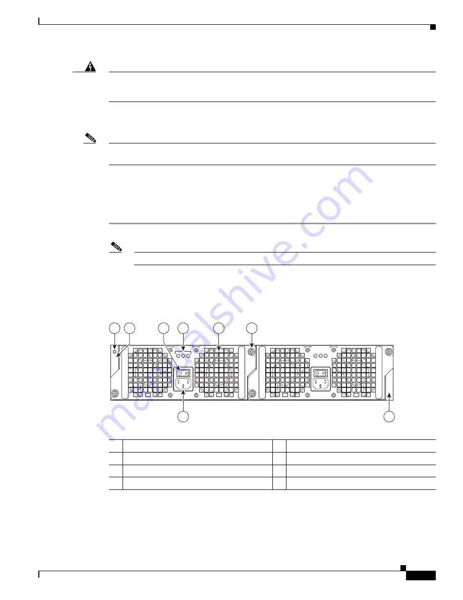
Figure 8-22
shows the various parts of the Cisco ASR 1002 Router AC power supply.
Figure 8-22
Cisco ASR 1002 Router AC Power Supply Labels
Step 2
Insert the AC power cable into the power supply AC inlet.
1
Chassis ESD socket
5
AC power supply fan
2
AC power supply slot number 0
6
AC power supply captive installation screw
3
AC power supply On (|) /Off (O) switch
7
AC power supply slot number 1
4
AC power supply LEDs
8
AC power inlet
OUTPUT INPUT
FAIL
OK
OK
FAN
OUTPUT INPUT
FAIL
OK
OK
FAN
This unit might have more than
one power supply connection.
All connections must be removed
to de-energize the unit.
This unit might have more than
one power supply connection.
All connections must be removed
to de-energize the unit.
0
1
8
7
280288
4
1
5
6
3
2


