Chapter III Vertical System
16
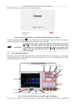
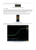
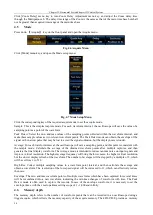
Fig. 3.11 Invert Example
3.9
Fine Scale
When any channel key CH1 ~ CH4 is pressed down, open the channel menu for Fine Scale on/off setting.
Click [Fine Scale] menu key to enable and disable the fine scale function of the channel. When Fine Scale is
disabled, operate the Scale knob of the channel, and the vertical range gear of the channel will be stepped
according to 1, 2 and 5. When Fine Scale is enabled, the vertical range gear of the channel will be added with
some fine tuning gears on the basis of steps 1, 2 and 5. The specific gears include:
The vertical range gears in case of 50Ω input impedance: 1 mV/div, 2 mV/div, 5 mV/div, 10 mV/div, 20
mV/div, 30 mV/div, 40 mV/div, 50 mV/div, 60 mV/div, 70 mV/div, 80 mV/div, 90 mV/div, 100 mV/div,
200 mV/div, 300 mV/div, 400 mV/div, 500 mV/div, 600 mV/div, 700 mV/div, 800 mV/div, 900 mV/div
and 1 V/div.
The vertical range gears in case of 1 MΩ input impedance: 1 mV/div, 2 mV/div, 5 mV/div, 10 mV/div,
20 mV/div, 30 mV/div, 40 mV/div, 50 mV/div, 60 mV/div, 70 mV/div, 80 mV/div, 90 mV/div, 100
mV/div, 200 mV/div, 300 mV/div, 400 mV/div, 500 mV/div, 600 mV/div, 700 mV/div, 800 mV/div, 900
mV/div, 1 V/div, 2 V/div, 3 V/div, 4 V/div, 5 V/div, 6 V/div, 7 V/div, 8 V/div, 9 V/div and 10 V/div.
3.10
Vertical range
Operate the Scale knob of any channel to set the vertical range gear of the corresponding channel. When Fine
Scale is disabled, the gear will be increased and decreased according to steps 1, 2 and 5 in case of clockwise
rotation and counterclockwise rotation respectively. When Fine Scale is enabled, the gear will be increased and
decreased according to fine tuning range in case of clockwise rotation and counterclockwise rotation respectively.
When the input impedance of the oscilloscope is 1 MΩ, the adjustment range of the vertical range gear is: 1
mV/div~10 V/div; When the input impedance is 50Ω, the adjustment range of the vertical range gear is: 1
mV/div~1 V/div.
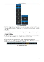
When adjusting the vertical range gear, the range information in the corresponding channel status bar will change
in real time, and the current gear will be displayed. You can quickly realize the vertical zoom of the waveform
through the multi-touch function of the capacitor screen.
3.11
Vertical offset
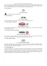
Operate the Position knob of any channel to set the vertical offset position of the corresponding channel. In case
of clockwise rotation, the waveform will move up; in case of counterclockwise rotation, it will move down.
When adjusting vertical position, the vertical position movement window will pop up on the left side of the screen,
and the current vertical offset will be displayed. You can quickly realize the vertical movement of the waveform
Содержание 4456 Series
Страница 1: ...4456 Series Digital Phosphor Oscilloscope User Manual China Electronics Technology Instruments Co Ltd...
Страница 10: ...VIII...
Страница 55: ...Chapter V Trigger System 45 Fig 5 51 RF Test Signal Example...
Страница 69: ...Chapter VII Mathematical Operation 59 Fig 7 10 Advanced Math Example...
Страница 71: ...Chapter VIII Display System 61 Fig 8 3 Wfm Palette Menu Fig 8 4 Normal Palette...
Страница 72: ...Chapter VIII Display System 62 Fig 8 5 Inverted Palette Fig 8 6 Temperature Palette...
Страница 75: ...Chapter VIII Display System 65 Fig 8 12 XY Display Example...
Страница 165: ...Chapter XI Protocol Analyzer Option 155 Fig 11 242 1553 Trigger and Analysis Example...


