Chapter XI Protocol Analyzer (Option)
97
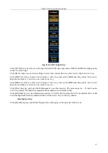
Fig. 11.64 SPI Config Menu
Click [SCLK] key, select the rise or fall edge from the SCLK edge type, and set MOSI and MISO sampling on the
SCLK rise or fall edge.
Click [SS Level] key to select Active High or Active Low, and set SS to be valid at Active High or Active Low.
Click [MOSI Level] key to select Active High or Active Low, and set the MOSI data line polarity bit to Active
High (Active High is 1) or Active Low (Active Low is 1).
Click [MISO Level] key to select Active High or Active Low, and set the MISO data line polarity bit to Active
High (Active High is 1) or Active Low (Active Low is 1).
Click [Word Size] key, and rotate the Multipurpose b to set the word size. The value range is 4 ~ 32, and it can be
set to 8 by default. The Word Size represents the bit number of each frame of data.
Click [Bit Order] key, set the transmission sequence to LS First (the low data bit will be transmitted first) or MS
First (the high data bit will be transmitted first), which will be set to LS First by default.
Bus display setup
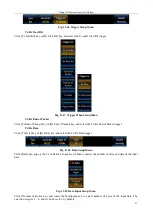
Click [Bus Display] key, and the Bus Display menu will pop up on the right side of the screen.
Содержание 4456 Series
Страница 1: ...4456 Series Digital Phosphor Oscilloscope User Manual China Electronics Technology Instruments Co Ltd...
Страница 10: ...VIII...
Страница 55: ...Chapter V Trigger System 45 Fig 5 51 RF Test Signal Example...
Страница 69: ...Chapter VII Mathematical Operation 59 Fig 7 10 Advanced Math Example...
Страница 71: ...Chapter VIII Display System 61 Fig 8 3 Wfm Palette Menu Fig 8 4 Normal Palette...
Страница 72: ...Chapter VIII Display System 62 Fig 8 5 Inverted Palette Fig 8 6 Temperature Palette...
Страница 75: ...Chapter VIII Display System 65 Fig 8 12 XY Display Example...
Страница 165: ...Chapter XI Protocol Analyzer Option 155 Fig 11 242 1553 Trigger and Analysis Example...


