Chapter XVIOscilloscope Probe (Option)
204
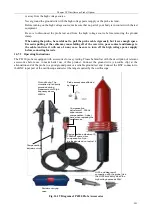
Power adapter
Crocodile clip
Hook
Input cable
Differential mode input voltage
Common mode input voltage
Over-range indicator
Power indicator
Attenuation switch
Probe body
Power
interface
Output cable
Fig. 16.22 Diagram of P8050 Probe Accessories
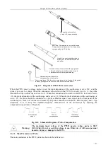
When the P8050 high voltage differential probe is used, the input impedance of the oscilloscope is set to 1M
Ω
, the
probe type is set to voltage, and the probe attenuation is set to the same as that of the P8050.
The P8050 high voltage differential probe is easy to use, but users who are not familiar with this product should
read this manual completely before starting the operation:
1
)
Make sure the input power supply voltage of the power adapter is normal before use.
2
)
The amplitude of the measured voltage should be estimated before test. If it exceeds the voltage range, the
probe may be damaged.
3
)
Connect the probe output BNC terminal to the oscilloscope or other measuring instrument and then connect
the input terminal to the test hook clamp to be used.
Содержание 4456 Series
Страница 1: ...4456 Series Digital Phosphor Oscilloscope User Manual China Electronics Technology Instruments Co Ltd...
Страница 10: ...VIII...
Страница 55: ...Chapter V Trigger System 45 Fig 5 51 RF Test Signal Example...
Страница 69: ...Chapter VII Mathematical Operation 59 Fig 7 10 Advanced Math Example...
Страница 71: ...Chapter VIII Display System 61 Fig 8 3 Wfm Palette Menu Fig 8 4 Normal Palette...
Страница 72: ...Chapter VIII Display System 62 Fig 8 5 Inverted Palette Fig 8 6 Temperature Palette...
Страница 75: ...Chapter VIII Display System 65 Fig 8 12 XY Display Example...
Страница 165: ...Chapter XI Protocol Analyzer Option 155 Fig 11 242 1553 Trigger and Analysis Example...

