Chapter XVIOscilloscope Probe (Option)
197
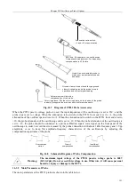
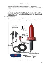
Probe front end:
Fully enclosed design for safer
use
BNC end: Connected to the oscilloscope
Compensation adjustment: For frequency
compensation in X100 state
Hook: Use a retractable and extended
probe to make your measurements
easier and safer
Ground clamp: Use a crocodile-type ground
clamp to reliably ground the probe for safe
operation and correct signal reading
Adjustment rod: Adjust the
compensation of the probe
Color ring sleeve: Put the color ring sleeve on both ends of the probe
to easily distinguish the probes used in different channels
Fig. 16.13 Diagram of P9558 Probe Accessories
When the P9558 probe is used, the input impedance of the oscilloscope is set to 1M
Ω
, the probe type is set to
voltage, and the probe attenuation is set to ×100. To avoid the error caused by the probe connection, the probe
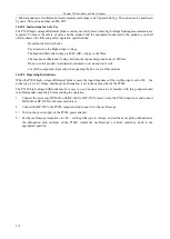
should be connected to a probe calibration square wave signal on the front panel of the oscilloscope, with about 1
kHz frequency and 3 Vpp amplitude, so as to keep flat amplitude-frequency characteristics of the oscilloscope by
adjusting the compensation capacitance of the probe.
Fig. 16.14 Schematic Diagram of Probe Compensation
Warning:
The maximum input voltage of the P558 high voltage single end probe is
3000V(DC+ACpk). Do not exceed this voltage in use. Otherwise, it will cause
personal hazard or injury or damage to the DUTs.
16.5.2 Main Parameters of Probe
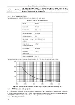
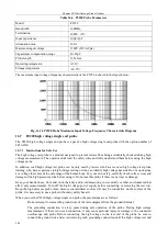
The main parameters of the P9558 probe are shown in the table below.
Over-compen
sation
Correct
compensation
Insufficient
compensation
Содержание 4456 Series
Страница 1: ...4456 Series Digital Phosphor Oscilloscope User Manual China Electronics Technology Instruments Co Ltd...
Страница 10: ...VIII...
Страница 55: ...Chapter V Trigger System 45 Fig 5 51 RF Test Signal Example...
Страница 69: ...Chapter VII Mathematical Operation 59 Fig 7 10 Advanced Math Example...
Страница 71: ...Chapter VIII Display System 61 Fig 8 3 Wfm Palette Menu Fig 8 4 Normal Palette...
Страница 72: ...Chapter VIII Display System 62 Fig 8 5 Inverted Palette Fig 8 6 Temperature Palette...
Страница 75: ...Chapter VIII Display System 65 Fig 8 12 XY Display Example...
Страница 165: ...Chapter XI Protocol Analyzer Option 155 Fig 11 242 1553 Trigger and Analysis Example...


