Chapter XI Protocol Analyzer (Option)
118
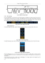
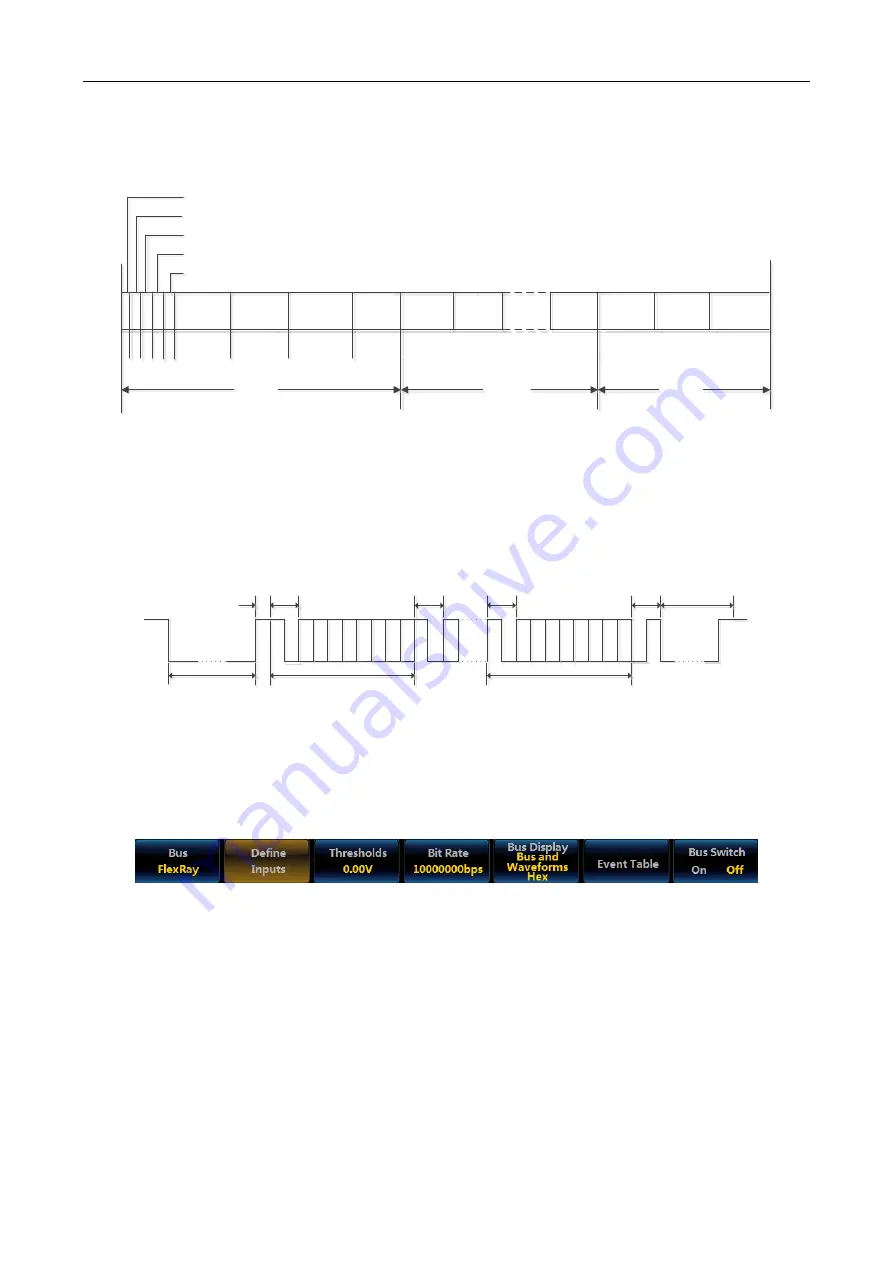
The FlexRay bus frame is composed of the Header Segment, Payload Segment and Trailer Segment, as shown in
the following figure. The Header Segment is composed of the indicator bit, frame ID, payload length and header
CRC and cycle count; the Payload Segment is composed of number of bytes between 0 and 254; the Trailer
Segment is composed of 3-byte CRC, which can be triggered on the header, frame type, identifier, cycle count,
complete header field, data, identifier and data, frame end and error.
1 1 1 1 1
7 bits
0...254 bytes
11 bits
11 bits
6 bits
24 bits
Reserved bit
Payload preamble indicator
Null frame indicator
Sync frame indicator
Startup frame indicator
Frame ID
Payload
length
Header
CRC
Cycle
count
Data0
Data1
Data n
CRC
CRC
CRC
Header Segment
Payload Segment
Trailer
Segment
Fig. 11.127 FlexRay Frame Format
The FlexRay frame includes static and dynamic frames. The decoding/coding sequences of static and dynamic
frames are as shown in Fig. 2. The TSS is a transmission start sequence, which is a period of low level. The FSS is
a frame start sequence, which is a period of high level and after the TSS. The BSS is a byte start sequence, which
provides timing information for a period of high level and low level. The FES is a frame end sequence, which is a
low level and a high level, after the effective data bit. If it is a dynamic frame, there is also a DTS sequence after
the FES, and the DTS is a dynamic tail sequence to prevent premature judgment of idle bus.
TSS
FSS
BSS
BSS
BSS
FES
DTS
1
st
byte sequence
Last byte sequence
Dynamic Frame with DTS
Fig. 11.128 FlexRay Frame Sequence
11.6.1 FlexRay bus setting
Press down
【
Bus
】
key in the Function Area on the front panel, and the Bus setup menu will pop up on the lower
screen (the menu will be based on the I2C bus). Click [Bus] menu key, and the Type selection menu will pop up
on the right side of the screen (the menu will be based on the I2C bus). Click [FlexRay] menu key and select the
FlexRay bus type, and it will be switched to the FlexRay Bus setup menu at the bottom of the screen:
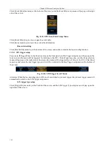
Fig. 11.129 FlexRay Bus Setup Level1 Menu
Define inputs setup
Click [Define Inputs] menu key, and the FlexRay Input setup menu will pop up on the right side of the screen:
Содержание 4456 Series
Страница 1: ...4456 Series Digital Phosphor Oscilloscope User Manual China Electronics Technology Instruments Co Ltd...
Страница 10: ...VIII...
Страница 55: ...Chapter V Trigger System 45 Fig 5 51 RF Test Signal Example...
Страница 69: ...Chapter VII Mathematical Operation 59 Fig 7 10 Advanced Math Example...
Страница 71: ...Chapter VIII Display System 61 Fig 8 3 Wfm Palette Menu Fig 8 4 Normal Palette...
Страница 72: ...Chapter VIII Display System 62 Fig 8 5 Inverted Palette Fig 8 6 Temperature Palette...
Страница 75: ...Chapter VIII Display System 65 Fig 8 12 XY Display Example...
Страница 165: ...Chapter XI Protocol Analyzer Option 155 Fig 11 242 1553 Trigger and Analysis Example...


