Chapter III Vertical System
13
In order to avoid the error caused by the probe connection, the probe shall be connected to a probe calibration
square wave signal on the front panel, with about 1 kHz frequency and 3 Vpp amplitude, so as to keep flat
amplitude-frequency characteristics of the oscilloscope by adjusting the adjustable capacitance of the probe.
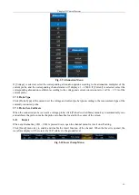
Fig. 3.4 Schematic Diagram of Probe Compensation
Warning:
The max. measured voltage of the passive voltage probe is 300 V CATII. Never
exceed this voltage during use. Otherwise, it will cause personal hazard or injury
or damage to the DUTs.
3.3
Channel status
When any channel key CH1-CH4 is pressed down, open the channel menu for on/off status setting.
When the channel is to be closed, press down the channel key to automatically open the corresponding channel
and channel menu. When the channel menu is opened, press down the channel key to automatically close the
corresponding channel.
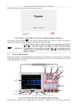
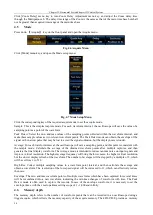
Fig. 3.5 Channel Status Setup Menu
Click [Channel1] menu key, and the channel can be switched between on/off status to realize the on/off function
of the channel.
When the channel is opened, the corresponding channel key indicator lamp will light up, and the corresponding
channel information, including the vertical scale, termination, coupling status, invert status and probe attenuation
coefficient will be displayed at the bottom status bar of the screen. When the channel is closed, the indicator lamp
will go out, and no channel information will be displayed in the status bar.
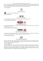
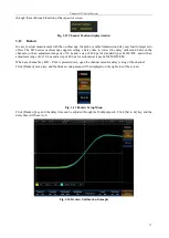
Fig. 3.6 Channel status indication column
3.4
Coupling
Set the coupling mode to filter out unnecessary signals. For example, the measured signal is a signal with a DC
offset.
When the coupling mode is
“
DC
”:
Both the DC component and the AC component of the measured
signal can pass through.
When the coupling mode is
“
AC
”:
Only the AC component of the measured signal can pass through.
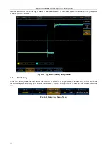
When any channel key CH1 ~ CH4 is pressed down, open the channel menu for coupling setting of the channel.
Click [Coupling] menu key, and the channel can be switched between DC and AC coupling. In addition, the
corresponding channel status bar will be displayed as DC or AC.
3.5
Termination
The oscilloscope provides two input impedances: 1 MΩ and 50Ω.
1 MΩ: In this case, the input impedance of the oscilloscope is very high, and the current flowing into the
oscilloscope from the measured circuit can be ignored.
50Ω: Make the oscilloscope match with the equipment with an output impedance of 50Ω.
When any channel key CH1 ~ CH4 is pressed down, open the channel menu for input impedance setting of the
channel.
Over-compensation
Correct compensation
Insufficient compensation
Содержание 4456 Series
Страница 1: ...4456 Series Digital Phosphor Oscilloscope User Manual China Electronics Technology Instruments Co Ltd...
Страница 10: ...VIII...
Страница 55: ...Chapter V Trigger System 45 Fig 5 51 RF Test Signal Example...
Страница 69: ...Chapter VII Mathematical Operation 59 Fig 7 10 Advanced Math Example...
Страница 71: ...Chapter VIII Display System 61 Fig 8 3 Wfm Palette Menu Fig 8 4 Normal Palette...
Страница 72: ...Chapter VIII Display System 62 Fig 8 5 Inverted Palette Fig 8 6 Temperature Palette...
Страница 75: ...Chapter VIII Display System 65 Fig 8 12 XY Display Example...
Страница 165: ...Chapter XI Protocol Analyzer Option 155 Fig 11 242 1553 Trigger and Analysis Example...

