Chapter II About the 4456 Series Digital Phosphor Oscilloscope
6
Ports, Logic Analyzer Extended Ports, Waveform Generator Extended Ports, 1kHz Calibration Signal, Screen
Display Area, Multipurpose Setup Area, Feature Setup Area, Run Control Setup Area, Horizontal System Setup
Area, Trigger System Setup Area, Vertical System Setup Area, Input Channels Area, etc.
2.2.1 Power button
Fig. 2.4 Power button
【
】
: For instrument poweron and poweroff.
2.2.2 Front USB Ports
Fig. 2.5 Front USB Ports
2 front USB2.0 HOST ports for insertion of mouse, keyboard and USB storage devices.
2.2.3 Logic analyzer extended ports
Fig. 2.6 Logic Analyzer Ports
The logic analyzer extended ports are used for signal input of 16 digital channels, which will be opened when the
4456-H01 option is selected.
2.2.4 Waveform generator extended ports
Fig. 2.7 Waveform Generator Ports
The waveform generator extended ports are used for the waveform output of 1 channel, with 50Ω output
impedance. The extended ports will be opened when the 4456-H02 option is selected.
2.2.5 1 kHz Calibration Signal
Fig. 2.8 1kHz Calibration Signal
The output probe square wave calibration signal, with about 1 kHz frequency and 3 Vpp amplitude, which is
mainly used for probe calibration and keeping flat amplitude-frequency characteristics of the oscilloscope by
adjusting the adjustable capacitance of the probe.
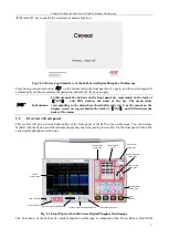
2.2.6 Screen Display Area
The Screen Display Area is an interaction window between the oscilloscope and the user, and information
including waveform and measurement result will be provided through it. The Screen Display Area of the
oscilloscope is mainly composed of the Horizontal Status Display Area, Running Status Display Area, Waveform
Display Area, Measurement Result Display Area, Vertical Status Display Area, Trigger Status Display Area,
System Time Display Area, Level1 Menu, Level2 Menu andLevel3 Menu.
Содержание 4456 Series
Страница 1: ...4456 Series Digital Phosphor Oscilloscope User Manual China Electronics Technology Instruments Co Ltd...
Страница 10: ...VIII...
Страница 55: ...Chapter V Trigger System 45 Fig 5 51 RF Test Signal Example...
Страница 69: ...Chapter VII Mathematical Operation 59 Fig 7 10 Advanced Math Example...
Страница 71: ...Chapter VIII Display System 61 Fig 8 3 Wfm Palette Menu Fig 8 4 Normal Palette...
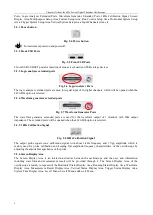
Страница 72: ...Chapter VIII Display System 62 Fig 8 5 Inverted Palette Fig 8 6 Temperature Palette...
Страница 75: ...Chapter VIII Display System 65 Fig 8 12 XY Display Example...
Страница 165: ...Chapter XI Protocol Analyzer Option 155 Fig 11 242 1553 Trigger and Analysis Example...

