Chapter V Trigger System
42
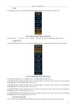
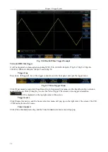
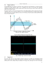
Fig. 5.43 Schematic Diagram of Trigger Holdoff
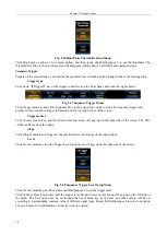
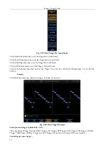
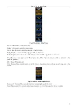
Click [Mode&Sensitivity] menu key, and open the Trigger Mode setup menu:
Fig. 5.44 Mode Menu
Click [Holdoff] key to set the trigger holdoff time through the Multipurpose b, or directly input the trigger holdoff
time through the numeric keypad. The adjustment range of the holdoff time is 6.4 ns ~ 12.8 s.
5.5
Trigger mode
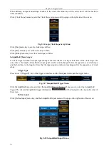
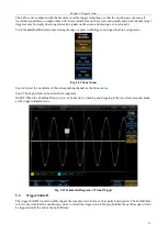
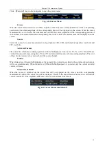
The 4456 series oscilloscope includes three trigger modes: Auto, Normal, and Single, and the currently selected
trigger mode will be displayed in the top status indication column.
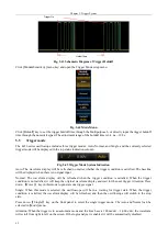
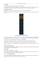
Fig. 5.45 Trigger Mode System Indication
Auto: The waveform display will be refreshed no matter whether the trigger condition is satisfied. The baseline
will be displayed when there is no signal input.
Normal: The waveform display will be refreshed when the trigger condition is satisfied. When the trigger
condition is not satisfied, it will keep the original waveform display and wait for the next trigger. Attention: Press
down
【
Force
】
key in this mode to generate one trigger signal.
Single: When this mode is selected, the oscilloscope will be in a waiting for trigger state. When the trigger
condition is satisfied, the waveform display will be refreshed, and then the oscilloscope will switch to the stop
state.
Press down
【
Single
】
key on the front panel to select the single trigger mode. The Auto and Normal can be
selected in [Mode] menu.
Attention: When the trigger is in an automatic mode and the time base is 100 ms/div ~ 1,000 s/div, the waveform
will scroll from right to left on the screen. If the logic analyzer is enabled, it will be automatically disabled.
Holdoff time
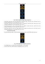
Trigger On
Содержание 4456 Series
Страница 1: ...4456 Series Digital Phosphor Oscilloscope User Manual China Electronics Technology Instruments Co Ltd...
Страница 10: ...VIII...
Страница 55: ...Chapter V Trigger System 45 Fig 5 51 RF Test Signal Example...
Страница 69: ...Chapter VII Mathematical Operation 59 Fig 7 10 Advanced Math Example...
Страница 71: ...Chapter VIII Display System 61 Fig 8 3 Wfm Palette Menu Fig 8 4 Normal Palette...
Страница 72: ...Chapter VIII Display System 62 Fig 8 5 Inverted Palette Fig 8 6 Temperature Palette...
Страница 75: ...Chapter VIII Display System 65 Fig 8 12 XY Display Example...
Страница 165: ...Chapter XI Protocol Analyzer Option 155 Fig 11 242 1553 Trigger and Analysis Example...


