Chapter III Vertical System
17
through the multi-touch function of the capacitor screen.
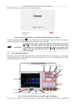
Fig. 3.12 Channel Position display window
3.12
Deskew
In case of actual measurement with the oscilloscope, the probe or cable transmission delay may lead to larger zero
offset. The 4456 series oscilloscope supports setting a delay time to correct the delay calibration between the
channels, with an adjustment range of ±150 ns and a step of 400 ps for standard types 4456C/D/E, and with an
adjustment range of ±150.4 ns and a step of 800 ps for economical types 4456CM/DM/EM.
When any channel key CH1 ~ CH4 is pressed down, open the channel menu for delay setting of the channel.
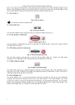
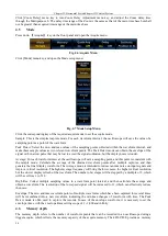
Click [Deskew] menu key, and the Deskew setup menu will be displayed on the right side of the screen:
Fig. 3.13 Deskew Setup Menu
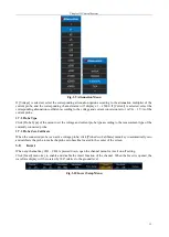
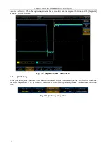
Click [Deskew] key, and the delay time can be adjusted through the Multipurpose b. Click [Set to 0s] key, and the
delay time will be set to 0.
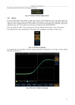
Fig. 3.14 Deskew Calibration Example
Содержание 4456 Series
Страница 1: ...4456 Series Digital Phosphor Oscilloscope User Manual China Electronics Technology Instruments Co Ltd...
Страница 10: ...VIII...
Страница 55: ...Chapter V Trigger System 45 Fig 5 51 RF Test Signal Example...
Страница 69: ...Chapter VII Mathematical Operation 59 Fig 7 10 Advanced Math Example...
Страница 71: ...Chapter VIII Display System 61 Fig 8 3 Wfm Palette Menu Fig 8 4 Normal Palette...
Страница 72: ...Chapter VIII Display System 62 Fig 8 5 Inverted Palette Fig 8 6 Temperature Palette...
Страница 75: ...Chapter VIII Display System 65 Fig 8 12 XY Display Example...
Страница 165: ...Chapter XI Protocol Analyzer Option 155 Fig 11 242 1553 Trigger and Analysis Example...


