Chapter XVIOscilloscope Probe (Option)
221
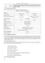
Avoid fire or personal injury
Connect and pull out correctly.
Replace the battery correctly.
Do not operate without the cover.
Avoid the exposed circuits.
You must ensure that all equipment is well grounded during operation.
Do not operate in a humid environment.
Do not operate in a flammable environment.
16.15.2 Operating Instructions
When the AP622 current probe is used, the input impedance of the oscilloscope is set to 1M
Ω
, the probe type is
set to current, and the probe attenuation is set to the same as that of the AP622.
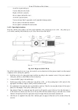
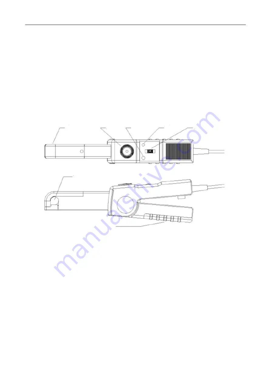
Jaw
Zero
adjustm
ent knob
Power
indicator
Overload
indicator
Switch and
range selection
Jaw
Battery box
Fig. 16.32 Diagram of AP622 Probe
The AP622 current probe is easy to use, but users who are not familiar with this product should read this manual
completely before starting the operation:
1
)
Push the switch to the appropriate range position according to the measured current. The power indicator
turns green and the overload indicator does not light up.
2
)
Connect the BNC plug to the oscilloscope.
3
)
Oscilloscope setting: Set the oscilloscope
’
s impedance to 1M
Ω
, set the coupling mode to DC, and select the
appropriate oscilloscope range according to the measured current.
4
)
Zero adjustment: Zero adjustment is required before each test. Turn the zero adjustment knob of the current
probe to set the display value on the oscilloscope to zero.
5
)
Measurement: Open the clamp and pass the tested wire through the center of the jaw. Note that the diameter
of the tested wire cannot exceed the size of the jaw. When the measurement range is exceeded, the overload
indicator will light up. Select the appropriate range and repeat the zero adjustment measurement.
6
)
After the test is completed, disconnect the conductor power supply and then take out the conductor from the
card slot.
Содержание 4456 Series
Страница 1: ...4456 Series Digital Phosphor Oscilloscope User Manual China Electronics Technology Instruments Co Ltd...
Страница 10: ...VIII...
Страница 55: ...Chapter V Trigger System 45 Fig 5 51 RF Test Signal Example...
Страница 69: ...Chapter VII Mathematical Operation 59 Fig 7 10 Advanced Math Example...
Страница 71: ...Chapter VIII Display System 61 Fig 8 3 Wfm Palette Menu Fig 8 4 Normal Palette...
Страница 72: ...Chapter VIII Display System 62 Fig 8 5 Inverted Palette Fig 8 6 Temperature Palette...
Страница 75: ...Chapter VIII Display System 65 Fig 8 12 XY Display Example...
Страница 165: ...Chapter XI Protocol Analyzer Option 155 Fig 11 242 1553 Trigger and Analysis Example...


