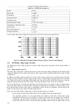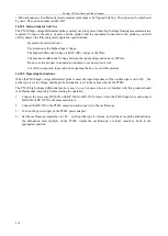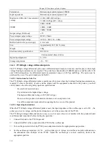
Chapter XVIOscilloscope Probe (Option)
201
is away from the high voltage source.
Never ground the ground wire with the high voltage power supply or the probe test end.
Before turning on the high voltage source, make sure that no part of your body is in contact with the test
equipment.
Be sure to disconnect the probe test end from the high voltage source before removing the ground
clamp.
When using the probe, be careful not to pull the probe cable vigorously, but leave enough space.
Excessive pulling of the cable may cause falling off of the core wire, poor contact and damage to
the cable. And use it with care. In any case, be sure to turn off the high voltage power supply
before connecting for tests.
16.7.2 Operating Instructions
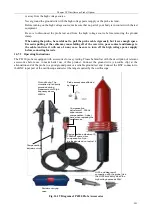
The P4220 probe is equipped with accessories for easy testing. Please be familiar with the description of relevant
accessories before use to make better use of this product. Connect the ground wire (crocodile clip) at the
attenuation end of the probe to a good ground point or a reliable ground test end. Connect the BNC connector to
the BNC input port of the oscilloscope and select the range required by the oscilloscope.
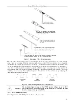
Probe accessories affected
by the test
Compensation
adjustment 1: 200Hz
square wave
compensation. Adjust
here when replacing the
oscilloscope
Crocodile clip: The
crocodile clip is directly
grounded during
measurement of high
frequency above
40MHz
Compensation adjustment 2:
200kHz square wave
compensation. Non-
professionals do not adjust it.
Compensation
adjustment rod
Portable carrying
case
HI-25 and diagram of
connection with the probe. Use
the HI-25 accessory when the
high voltage exceeds 25kV
Fig. 16.19 Diagram of P4220 Probe Accessories
Содержание 4456 Series
Страница 1: ...4456 Series Digital Phosphor Oscilloscope User Manual China Electronics Technology Instruments Co Ltd...
Страница 10: ...VIII...
Страница 55: ...Chapter V Trigger System 45 Fig 5 51 RF Test Signal Example...
Страница 69: ...Chapter VII Mathematical Operation 59 Fig 7 10 Advanced Math Example...
Страница 71: ...Chapter VIII Display System 61 Fig 8 3 Wfm Palette Menu Fig 8 4 Normal Palette...
Страница 72: ...Chapter VIII Display System 62 Fig 8 5 Inverted Palette Fig 8 6 Temperature Palette...
Страница 75: ...Chapter VIII Display System 65 Fig 8 12 XY Display Example...
Страница 165: ...Chapter XI Protocol Analyzer Option 155 Fig 11 242 1553 Trigger and Analysis Example...

