


2
Remote Control
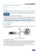
2.1 Remote control basis
24
controller‘s service, and then the controller will initiate an interruption to enter the corresponding
interruption handler. As shown in Figure 2.4, an SRQ is usually initiated by one or more status bytes and
the 2
nd
, 3
rd
, 4
th
, 5
th
or 7
th
bits of the associated enable register (SRE). These data bits are composed of
the advanced register, error queue, or output buffer area further. In order to use all the service requests
as much as possible, all data bits of the enable registers SRE and ESE shall be set to 1.
Example: When the command "*OPC" is used after sweep, the SRQ signal will be generated.
a)
Recall the write function InstrWrite and write command ―*ESE 1‖, and set the ESE bit0
(operation is completed).
b)
Recall the write function InstrWrite and write command ―*ESE 32‖, and set the SRE bit5 (ESB).
c) Recall the write
function InstrWrite and write command ―*INIT;*OPC‖, and generate the SRQ
signal after operation is completed.
The instrument will generate an SRQ after settings are completed.
The SRQ can only be initiated by the instrument, and the controller program shall allow sending the
service request to it when the instrument has an error, and it will be processed by a special interruption
handler. For specific routine, please refer to Section 4.2.1.1. Service Request.
2) Series query
Similar to the command *STB, the series query can be used to query the status byte of the instrument.
The series query adopts the interface message mode, therefore, the query is fast. The IEEE 488.2
defines the specific series query method. This method is mainly used to quickly obtain the status of one
or more instruments connected with the controller in the test system.
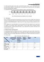
3) Parallel query
The controller can send an information bit to the USB cable through a command, and query 8
instruments in the test system. The data configured on
the USB cable of the instrument is logic ―0‖ or ―1‖.
Except that the SRE register determines the conditions generating the SRQ, perform parallel query to
check AND operation of data bit of the enable register (PPE) and the STB register. The result will be
made as the response result and sent to the parallel query controller through OR operation and bit
reverse, and it can also be obtained through the command *IST.
During parallel query, set the instrument to the parallel query status through the command PPC firstly,
and this command will allocate a USB cable to the instrument and determine whether the data bit is
reversed in response. Use the PPE register during execution of the parallel query. The parallel query is
mainly used to quickly position which instrument sends the service request by the controller. Accordingly,
the same value shall be set for the registers SRE and PPE.
4) Instrument status query
Query each part of the status register through following two commands:
Command ―*IDN?‖ for querying the high-level register;
Status system command for querying the SCPI register (e.g. STATus:QUEStionable...).
The returned value of the queried register is usually in decimal format, which is used by the controller
program for detection. In order to obtain a more detailed description of the SRQ cause, the parallel query
will be carried out after the SRQ generally.
Description of response data bit
Содержание 1465 Series
Страница 1: ...1465 series Signal Generator Programming Manual...
Страница 2: ......
Страница 5: ......
Страница 39: ......
Страница 127: ......


