


2
Remote Control
2.1 Remote control basis
23
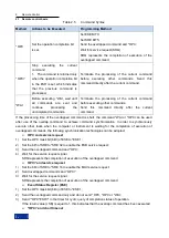
Table 2.9 STAT: QUES: FREQ Register Description
Data Bit
Meaning
0
OVEN COLD
If the reference oscillator does not reach its operating temperature, set this bit. At the
same time, the user interface shows the prompt message ―OCXO‖.
1
Local oscillator UNL
If the local oscillator is unlocked, set this bit. At the same time, the user interface shows
the prompt message ―LO UNL‖.
2..7
Not used.
8
External reference
If an external reference oscillator is set, but the available external reference signal is not
actually connected, set this bit. At this time, the frequency synthesizer is unlocked and the
frequency accuracy is low.
9..14
Not used.
15
This bit is always 0.
5) STAT: QUES: POW register
This register contains information about power overload when the instrument is operated. Each active
channel corresponds to a separate power register. The value of this register can be read via the
command ―STATus:QUEStionable: POWer:CONDition?‖ or ―STATus:QUEStionable: POWer [:EVENt]?‖.
The description of the status register is as shown in the following Table 2.16.
Table 2.10 STAT: QUES: POW Register Description
Data Bit
Meaning
0
Overload
If the power of RF input signal is overloaded, set this bit. This will cause signal distortion
without damaging the instrument, and at the same time, the user interface will show the
prompt message ―RF overload‖.
3
Input overload
If the signal power of RF input connector is out of the rated range, set this bit. At the same
time, the user interface shows the prompt message ―Input overload‖. The RF input and
the input mixer are separated to protect the instrument. In case of repeated
measurement, reduce the power level of RF input connector.
4..14
Not used.
15
This bit is always 0.
2.1.5.4 Application of status reporting system
The status reporting system is used to monitor the status of one or more instruments in the test system.
To correctly realize the function of the status reporting system, the controller in the test system must
receive and evaluate the information of all instruments. The standard methods applied include:
1) Query the service request (SRQ) initiated by the instrument;
2) Perform serial poll of all instruments in the bus system, which is initiated by the controller in the
system in order to find out the initiator and reason of the service request.
3) Perform parallel query of all instruments;
4) Query of the status of specific instrument by remote control command;
5) Query of the error queue.
1) Service request
In some cases, the instrument will send a service request (SRQ) to the controller to obtain the
Содержание 1465 Series
Страница 1: ...1465 series Signal Generator Programming Manual...
Страница 2: ......
Страница 5: ......
Страница 39: ......
Страница 127: ......


