


2
Remote Control
2.1 Remote control basis
21
associated STB bit changes to 1 from 0, a service request (SRQ) will be generated. The common
command ―*SRE‖ is used to set the SRE, and the common command ―*SRE? ‖ is used to read the SRE.
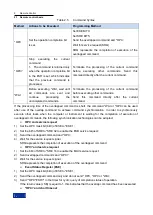
The status byte is described in the following Table 2.6 Description of the Status Byte:
Table 2.6 Description of Status Bytes
Data Bit
Meaning
0..1
Not used.
2
The error queue is non-null
Set the bit if a new error is inserted into the error queue. If the associated SRE bit enables
the bit and a a new error is generated in the error queue, a service request will be generated
to identify the error and query the error information. This method effectively reduces the
error in remote control.
3
Data sum bit of the status query register
The bit can be set if the event bit of the status query register and the associated enable bit
are set to 1. The bit represents a queriable status of the instrument, and the specific status
information of the instrument can be obtained by querying the status query register of the
status register.
4
MAV bit (message available)
Set the bit if the output queue information is readable. Use the bit when the controller
queries the instrument information.
5
ESB bit
Data sum bit of the event status register. The bit can be set if one bit of the event status
register is set and the enable event enables the corresponding bit in the register. If the
position bit is 1, it means that the instrument has a severe error, and the specific error
information can be obtained by querying the event status register.
6
MSS bit (master status summary bit)
Set the bit if the instrument triggers the service request.
7
Data sum bit of the operation status register
The bit can be set if the event bit of the operation status register and the corresponding
enable bit are set to 1. This bit indicates that the instrument executes an operation, and the
specific operation type can be obtained by querying the operation status register.
2) Event status register (ESR) and event status enable register (ESE)
For definition of ESR, refer to IEEE488.2. The event status register (ESR) can be read through the
command ―*ESR?‖. The ESE is an enable part of the SCPI register. If one position is set to 1 and one
data bit in the responsive ESR changes to 1 from 0, the ESB bit of the STB will be set to 1. Set and read
the ESE through the command ―*ESE‖ and the command ―*ESE?‖ respectively.
Table 2.7 Description of Event Status Bytes
Data Bit
Meaning
0
Operation completed
The bit can be set when the the previous commands have been executed and the
command *OPC has been received.
1
Not used.
2
Query error
This bit is set if the controller reads the instrument data without sending a query command
or sends a new command without reading the query data. It means that a wrong query is
generated and the query can‘t be executed.
3
Instrument error
Set the bit if an instrument error is generated. Range of error code: -300~-399, or positive
error code. For details of specific error information, query relevant information in the error
queue.
4
Execution error
Содержание 1465 Series
Страница 1: ...1465 series Signal Generator Programming Manual...
Страница 2: ......
Страница 5: ......
Страница 39: ......
Страница 127: ......


