2. Installation procedures
- 23 -
7.1.6 Registration of detector
Ensure that the detector used is registered by the image capture computer, establish the communication
circuit, and set to the imaging enabled status. In this service manual, registration of the detector is
referred to as “detector registration” or “LINK.”
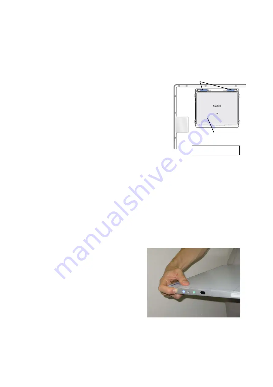
(1) Installing the fully charged battery
1) Align the battery insertion tabs with the groove on the rear panel
of the detector.
2) Install the battery in the detector.
3) While pressing on the battery from above, slide the lock switch to
the LOCK side.
Note:
* The status LED of the battery charger lights up green if the battery
is fully charged.
* The battery must be installed in the detector when either
wired connections or wireless connections are used.
How to remove the battery
1) With the battery held in place, slide the lock switch to the UNLOCK side.
2) The battery now pops up, and can be removed.
(2) Registering the detector
1) Press the power switch on the side of the detector for at least a second to turn on the power.
Note:
* Check that the blue LED on the detector lights.
*
Detector registration must be undertaken outside the patient environment. There must be no monitors
or reflective objects near the detector.
*
To turn off the power of the detector, hold down the power switch for 5 seconds.
2) Ensure that the distance between the infrared communication area on the side of the detector and the
signal sensing area on the infrared data communication unit is less than 30 cm.
Note:
* Make sure that the power of the image capture computer has been turned on and that link Controller
has started up.
Battery locks
Battery
Rear panel of detector
Содержание CXDI-80C
Страница 6: ...Note These measurements are only guidelines ...
Страница 10: ...1 1 O Ov ve er rv vi ie ew w 2 2 System diagram ...
Страница 48: ...2 Installation procedures 15 4 Handle unit option Corner pads Outer box Inner box ...
Страница 53: ...2 Installation procedures 20 7 Installation 7 1 Connections to the units 7 1 1 System connection diagram ...
Страница 82: ...2 Installation procedures 49 4 Battery Weight 0 25 kg Dimensional unit mm Dimensional tolerance 1 Scale 1 N ...
Страница 133: ...Rev 01 CONTENTS Detector unit 1 X ray interface box unit 2 Wiring unit 4 Handle unit 6 ...
Страница 134: ...Rev 01 Detector unit KEY NO PARTS NO Q TY DESCRIPTION MEMO 1 BA5 1230 000 2 Battery Connector Pad 1 1 ...


