


Link Section Planes
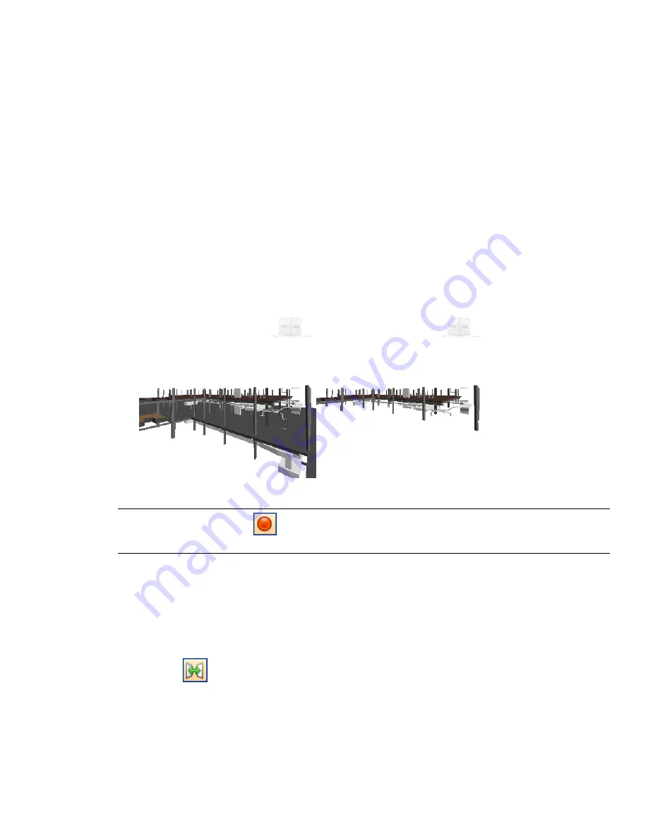
In Autodesk Navisworks, you can link any two section planes together, so they move as one. Doing this enables
you to quickly slice your model in real time. The slices can be used in viewpoints, viewpoint animations, and
object animations.
In practice, you should only link parallel planes together, such as top and bottom, left and right, front and back.
This is because linking together section planes that are at right angles to each other, and then moving them will
have no visible effect on the model.
Also, you may have unpredictable results if you try to link section planes that are aligned to lines, surfaces, or
view.
To link two parallel planes together
1
Begin by setting up two parallel section planes, for example, the first one aligned to Top, and the second
one aligned to Bottom. You can use the slider to adjust the position of each of the planes (that is how far
you want them separated in the slice).
2
Click the Link button.
3
Move the slider. Now when you move one of the section planes, the other one moves with it, effectively,
creating a slice through the model.
NOTE
You can click the Record
button on the Animation toolbar, and record a viewpoint animation showing
the model as it is sliced. You can also save the configured slice as a viewpoint, and return to it later.
Enable and Use Section Boxes
You can define a section box to focus your review on specific and limited areas of the model. Once you’ve set
the box size, you can use the X, Y, Z boxes on the Sectioning toolbar to move the box around the model. By
default, the range of box movement covers the entire extents of the model.
It is possible to restrict the range of the box movement, and set a finer resolution for sectioning large models.
The Set Range
button enables you to limit the range of the section box to the bounding box limits of the
currently selected items. Clicking this button with nothing selected resets the range back to default.
You can also specify the Step Size used to control the X, Y, Z boxes; it dictates the incremental value by which
the box moves when you single-click on the up/down arrows next to each box.
If the Step Size in not enabled, the box will move at percentage intervals when you single-click on the up/down
arrows.
Once defined, the box remembers its settings.
248 | Chapter 9 Use Viewpoints and Sectioning Modes
Содержание 507B1-90A211-1301 - NavisWorks Manage 2010
Страница 1: ...Autodesk Navisworks Manage 2010 User Guide March 2009 ...
Страница 12: ...xii Contents ...
Страница 14: ...2 Part 1 Welcome to Autodesk Navisworks Manage 2010 ...
Страница 64: ...52 Chapter 3 Installation ...
Страница 97: ...Get a Whole Project View 85 ...
Страница 98: ...86 Part 2 Get a Whole Project View ...
Страница 136: ...124 Chapter 5 Work with Files ...
Страница 178: ...To toggle ViewCube Click View Head Up Display ViewCube 166 Chapter 6 Explore Your Model ...
Страница 262: ...250 Chapter 9 Use Viewpoints and Sectioning Modes ...
Страница 270: ...258 Chapter 11 Work Within a Team ...
Страница 282: ...270 Chapter 12 Share Data ...
Страница 346: ...334 Chapter 14 Create Photorealistic Visualizations ...
Страница 460: ...448 Chapter 17 Autodesk Navisworks Reference ...
Страница 466: ...454 Glossary ...


