


To hide links without comments
1
Click Tools
➤
Global Options.
2
In the Options Editor, expand the Interface node, expand the Hyperlinks node, and click the Standard
Categories option.
3
On the Standard Categories page, select the Hide Icons Without Comments check box for all required link
categories.
By default, links without comments are also displayed.
4
Click OK.
Customize Links
You can customize the default appearance of links in Autodesk Navisworks. In particular, you can draw them in
3D, and you can add leader lines (arrows) pointing to the attachment point on the items. You can also choose
how to represent each link category (as an icon or as text).
Attachment Points
By default, links are attached to the default center of the item's bounding box.
You can override this with more convenient attachment points. If you add more than one attachment point,
the link is displayed attached to the closest attachment point to the camera during navigation. This allows you
to set up links so that they are always available for following when drawn in 3D mode during navigation, and
do not disappear behind objects.
To draw links in 3D mode
NOTE
In 3D mode links can become hidden by other objects in the scene when you are navigating.
1
Click Tools
➤
Global Options.
2
In the Options Editor, expand the Interface node, and click the Hyperlinks option.
3
On the Hyperlinks page, select the In 3D check box.
Links now float in 3D space just in front of their attachment points to the items.
4
Click OK.
To show leader lines
1
Click Tools
➤
Global Options.
2
In the Options Editor, expand the Interface node, and click the Hyperlinks option.
3
On the Hyperlinks page, Enter the X- and Y- distance in Leader Offset for the number of pixels to the right
and up that these leader lines will use. The default angle is 0. The recommended angle is 45.
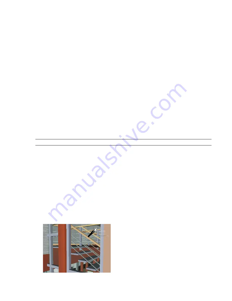
Links in the Scene Area have now leader lines pointing to the attachment point on the items.
Customize Links | 229
Содержание 507B1-90A211-1301 - NavisWorks Manage 2010
Страница 1: ...Autodesk Navisworks Manage 2010 User Guide March 2009 ...
Страница 12: ...xii Contents ...
Страница 14: ...2 Part 1 Welcome to Autodesk Navisworks Manage 2010 ...
Страница 64: ...52 Chapter 3 Installation ...
Страница 97: ...Get a Whole Project View 85 ...
Страница 98: ...86 Part 2 Get a Whole Project View ...
Страница 136: ...124 Chapter 5 Work with Files ...
Страница 178: ...To toggle ViewCube Click View Head Up Display ViewCube 166 Chapter 6 Explore Your Model ...
Страница 262: ...250 Chapter 9 Use Viewpoints and Sectioning Modes ...
Страница 270: ...258 Chapter 11 Work Within a Team ...
Страница 282: ...270 Chapter 12 Share Data ...
Страница 346: ...334 Chapter 14 Create Photorealistic Visualizations ...
Страница 460: ...448 Chapter 17 Autodesk Navisworks Reference ...
Страница 466: ...454 Glossary ...


