Programmable Logic
P846/EN PL/D
MiCOM P846
(PL) 7-7
Rules for Linking Symbols
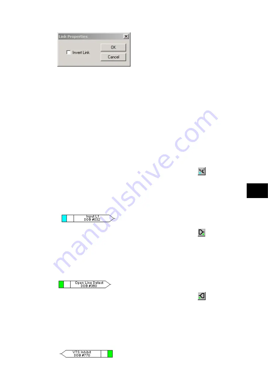
Links can only be started from the output of a signal, gate, or conditioner, and can only be
ended on an input to any element.
Since signals can only be either an input or an output then the concept is somewhat
different. In order to follow the convention adopted for gates and conditioners, input signals
are connected from the left and output signals to the right. The Editor will automatically
enforce this convention.
A link attempt will be refused where one or more rules would otherwise be broken. A link will
be refused for the following reasons:
•
An attempt to connect to a signal that is already driven. The cause of the refusal may
not be obvious, since the signal symbol may appear elsewhere in the diagram. Use
“Highlight a Path” to find the other signal.
•
An attempt is made to repeat a link between two symbols. The cause of the refusal may
not be obvious, since the existing link may be represented elsewhere in the diagram.
1.6.2
Opto signal properties
Opto Signal
Each opto input can be selected and used for programming in PSL. Activation of the opto
input will drive an associated DDB signal.
For example activating opto input L1 will assert DDB 032 in the PSL
PL
1.6.3
Input signal properties
Input Signal
Relay logic functions provide logic output signals that can be used for programming in PSL.
Depending on the relay functionality, operation of an active relay function will drive an
associated DDB signal in PSL.
For example DDB 360 be asserted in the PSL should the open line detector operate/trip.
1.6.4
Output signal properties
Output Signal
Relay logic functions provide logic input signals that can be used for programming in PSL.
Depending on the relay functionality, activation of the output signal will drive an associated
DDB signal in PSL and cause an associated response to the relay function
For example, if DDB 770 is asserted in the PSL, it will inhibit the voltage supervision
function.
Содержание MiCOM P846
Страница 2: ......
Страница 4: ......
Страница 5: ...Safety Section P846 EN SS H11 SS SAFETY SECTION...
Страница 6: ...P846 EN SS H11 Safety Section SS...
Страница 8: ...P846 EN SS H11 Safety Section SS 2 SS...
Страница 16: ...P846 EN IT D Introduction MiCOM P846 IT...
Страница 18: ...P846 EN IT D Introduction IT 1 2 MiCOM P846 IT...
Страница 26: ...P846 EN TD D Technical Data MiCOM P846 TD...
Страница 38: ...P846 EN GS D Getting Started MiCOM P846 GS...
Страница 58: ...P846 EN ST D Getting Started MiCOM P846 ST...
Страница 60: ...P846 EN ST D Settings ST 4 2 MiCOM P846 ST...
Страница 78: ...P846 EN OP D Operation MiCOM P846 OP...
Страница 104: ...P846 EN OP D Operation OP 5 26 MiCOM P846 OP...
Страница 106: ...P846 EN AP D Application Notes MiCOM P846 AP...
Страница 108: ...P846 EN AP D Application Notes AP 6 2 MiCOM P846 AP...
Страница 122: ...P846 EN AP D Application Notes AP 6 16 MiCOM P846 AP...
Страница 124: ...P846 EN PL D Programmable Logic MiCOM P846 PL...
Страница 126: ...P846 EN PL D Programmable Logic PL 7 2 MiCOM P846 PL...
Страница 144: ...P846 EN MR D Measurements and Recording MiCOM P846 MR...
Страница 146: ...P846 EN MR D Measurements and Recording MR 8 2 MiCOM P846 MR...
Страница 160: ...P846 EN FD D Firmware Design MiCOM P846 FD...
Страница 182: ...P846 EN CM D Commissioning MiCOM P846 CM...
Страница 228: ...P846 EN CM D Commissioning CM 10 46 MiCOM P846 CM...
Страница 230: ...P846 EN MT D Maintenance MiCOM P846 MT...
Страница 232: ...P846 EN MT D Maintenance MT 11 2 MiCOM P846 MT...
Страница 238: ...P846 EN TS D Troubleshooting MiCOM P846 TS...
Страница 240: ...P846 EN TS D Troubleshooting TS 12 2 MiCOM P846 TS...
Страница 252: ...P846 EN SC D SCADA Communications MiCOM P846 SC...
Страница 272: ...P846 EN SG D Symbols and Glossary MiCOM P846 SG...
Страница 280: ...P846 EN SG D Symbols and Glossary SG 14 8 MiCOM P846 SG...
Страница 282: ...P846 EN IN D Installation MiCOM P846 IN...
Страница 284: ...P846 EN IN D Installation IN 15 2 MiCOM P846 IN...
Страница 293: ...Installation P846 EN IN D MiCOM P846 IN 15 11 7 P846 CASE DIMENSIONS Figure 3 Case dimensions IN...
Страница 295: ...Installation P846 EN IN D MiCOM P846 IN 15 13 P1756ENa IN Figure 5 Model B with 32 output contacts and 24 digital inputs...
Страница 296: ...P846 EN IN D Installation IN 15 14 MiCOM P846 IN...
Страница 297: ......


