11
Tables
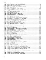
Table 1: Twisted Pair Ports on the AT-XEM2-12XT Line Card ............................................................................................22
Table 2: Link and Activity LEDs on the AT-XEM2-12XT Line Card ..................................................................................... 22
Table 3: Link and Activity LEDs on the AT-XEM2-12XS Line Card ..................................................................................... 24
Table 4: Link and Activity Status LEDs for the AT-XEM2-4QS Line Card ........................................................................... 25
Table 5: Link and Activity Status LED for the AT-XEM2-1CQ Line Card ............................................................................. 26
Table 6: Twisted Pair Cable for the NET MGMT Port on the Management Panel .............................................................. 28
Table 7: NET MGMT Port LED ............................................................................................................................................ 29
Table 8: PORT Parameter Format ....................................................................................................................................... 35
Table 9: Software and Hardware Releases ......................................................................................................................... 37
Table 10: Maximum Number of Trunk Ports Per Switch ...................................................................................................... 46
Table 11: Hardware Installation Procedures ........................................................................................................................ 62
Table 12: Switch Configuration Procedures ......................................................................................................................142
Table 13: Commands for Enabling the VCStack Feature ..................................................................................................151
Table 14: Example of Designating Trunk Ports .................................................................................................................154
Table 15: AT-XEM2 Line Cards and Fiber Optic Transceivers ..........................................................................................160
Table 16: AT-XEM2 Line Cards and Direct Connect Cables .............................................................................................163
Table 17: Product Dimensions ...........................................................................................................................................206
Table 18: Product Weights ................................................................................................................................................206
Table 19: Ventilation Requirements ...................................................................................................................................207
Table 20: Environmental Specifications .............................................................................................................................208
Table 21: AC Voltage and Frequency Requirements ........................................................................................................209
Table 22: DC Voltage Requirements .................................................................................................................................209
Table 23: Maximum Power Consumption (Watts) .............................................................................................................209
Table 24: Typical Power Savings in eco-friendly Mode (Watts) ........................................................................................209
Table 25: Maximum Power Supply Efficiency (Based on 100V Input Voltage) .................................................................210
Table 26: Heat Dissipation (British Thermal Units/Hour) ...................................................................................................210
Table 27: Product Certifications .........................................................................................................................................211
Table 28: Pin Signals for 1Gbps or 10Gbps ......................................................................................................................212
Table 29: RJ-45 Pin Signals for the Console Port on the Management Panel ..................................................................213
Table 30: RJ-45 Pin Signals for 10 or 100Mbps for the NET MGMT Port on the Management Panel ..............................213
Содержание AT-FAN08
Страница 10: ...Figures 10...
Страница 12: ...Tables 12...
Страница 16: ...Preface 16...
Страница 38: ...Chapter 1 Overview 38...
Страница 60: ...Chapter 2 Virtual Chassis Stacking 60...
Страница 80: ...Chapter 4 Installing the Chassis 80 Figure 32 Chassis Orientations in the Equipment Rack Continued...
Страница 82: ...Chapter 4 Installing the Chassis 82 Figure 34 Example of Adjusting the Equipment Rack Brackets...
Страница 104: ...Chapter 4 Installing the Chassis 104...
Страница 140: ...Chapter 5 Powering On the Chassis 140...
Страница 166: ...Chapter 7 Cabling the AT XEM2 Line Card Ports 166...
Страница 214: ...Appendix A Technical Specifications 214...


