AT-SBx908 GEN2 Installation Guide for Virtual Chassis Stacking
153
Designating Trunk Ports
This procedure explains how to designate the trunk ports of the switch.
The trunk is a physical network pathway, linking the switches together into
a stack. For guidelines, refer to “Stacking Guidelines” on page 41. Please
review the following information before performing this procedure:
There are no default trunk ports.
The VCStack feature has to be enabled on the switch for you to
designate trunk ports. For instructions, refer to “Enabling the
VCStack Feature” on page 151.
The commands for designating trunk ports are STACKPORT and
NO STACKPORT. You use the STACKPORT command to
designate ports as trunk ports, and the NO STACKPORT
command to remove the trunk function from ports. The commands
are performed in the port Interface modes.
Note
This procedure requires reseting the switch. Some network traffic
will be lost if the switch is connected to an active network.
Here are the general steps to designating trunk ports:
1. Start a local or remote management session on the switch.
2. Enter the Interface mode for ports that are to be trunk ports.
3. Issue the STACKPORT command to designate them as trunk ports.
4. Save your changes with the WRITE command.
5. Restart the switch with the REBOOT command.
6. Start a new management session.
7. Confirm the new trunk ports with the SHOW STACKPORT DETAIL
command.
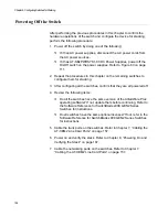
After designating and confirming the trunk ports, go to “Powering Off the
Switch” on page 156.
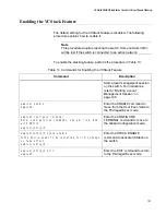
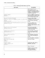
Table 14 on page 154 is an example of the procedure. It designates
port1.2.1 and port1.5.4 as trunk ports for the switch. For background
information on port numbering, refer to “Specifying Ports in the Command
Line Interface” on page 35.
Содержание AT-FAN08
Страница 10: ...Figures 10...
Страница 12: ...Tables 12...
Страница 16: ...Preface 16...
Страница 38: ...Chapter 1 Overview 38...
Страница 60: ...Chapter 2 Virtual Chassis Stacking 60...
Страница 80: ...Chapter 4 Installing the Chassis 80 Figure 32 Chassis Orientations in the Equipment Rack Continued...
Страница 82: ...Chapter 4 Installing the Chassis 82 Figure 34 Example of Adjusting the Equipment Rack Brackets...
Страница 104: ...Chapter 4 Installing the Chassis 104...
Страница 140: ...Chapter 5 Powering On the Chassis 140...
Страница 166: ...Chapter 7 Cabling the AT XEM2 Line Card Ports 166...
Страница 214: ...Appendix A Technical Specifications 214...


