Chapter 1: Overview
28
NET MGMT
Ethernet
Management
Port
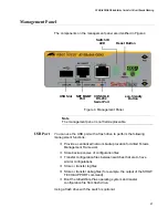
The switch uses the NET MGMT port as a separate routed eth0 interface.
The interface is not part of the switching matrix of the Ethernet line cards,
but the switch can route traffic in or out of the port from the line cards.
Here are the guidelines:
The port should only be used for initial configuration and
maintenance access to the switch.
The port has a standard 8-pin RJ-45 connector and operates at 10,
100, or 1000 Mbps in either half- or full-duplex mode.
The default setting for the port is Auto-Negotiation, which sets the
speed and duplex mode automatically. You may disable Auto-
Negotiation and configure the port manually.
The wiring configuration of the NET MGMT port is set
automatically with automatic MDIX detection. You may disable
automatic MDIX detection and set the wiring configuration
manually.
The port is referred to as eth0 in the management software.
The cable requirements for the port are listed in Table 6.
For instructions on how to configure the NET MGMT port, refer to the
Software Reference for SwitchBlade x908 Gen2 Switch.
Table 6. Twisted Pair Cable for the NET MGMT Port on the Management
Panel
Cable Type
10Mbps
100Mbps
1000Mbps
Standard TIA/EIA 568-B-
compliant Category 3 shielded
or unshielded cabling with 100
ohm impedance and a
frequency of 16 MHz.
Yes
Yes
No
Standard TIA/EIA 568-A-
compliant Category 5 or TIA/
EIA 568-B-compliant Enhanced
Category 5 (Cat 5e) shielded or
unshielded cabling with 100
ohm impedance and a
frequency of 100 MHz.
Yes
Yes
Yes
Standard TIA/EIA 568-B-
compliant Category 6 shielded
cabling.
Yes
Yes
Yes
Standard TIA/EIA 568-C-
compliant Category 6a shielded
cabling.
Yes
Yes
Yes
Содержание AT-FAN08
Страница 10: ...Figures 10...
Страница 12: ...Tables 12...
Страница 16: ...Preface 16...
Страница 38: ...Chapter 1 Overview 38...
Страница 60: ...Chapter 2 Virtual Chassis Stacking 60...
Страница 80: ...Chapter 4 Installing the Chassis 80 Figure 32 Chassis Orientations in the Equipment Rack Continued...
Страница 82: ...Chapter 4 Installing the Chassis 82 Figure 34 Example of Adjusting the Equipment Rack Brackets...
Страница 104: ...Chapter 4 Installing the Chassis 104...
Страница 140: ...Chapter 5 Powering On the Chassis 140...
Страница 166: ...Chapter 7 Cabling the AT XEM2 Line Card Ports 166...
Страница 214: ...Appendix A Technical Specifications 214...

