viii
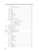
Keyboard........................................................................................................1-23
Windows 95 Keys ........................................................................1-23
FDD ...............................................................................................................1-24
HDD...............................................................................................................1-24
CD-ROM........................................................................................................1-25
Battery............................................................................................................1-25
Charger ..........................................................................................................1-26
DC-DC Converter...........................................................................................1-27
DC-AC Inverter..............................................................................................1-27
LCD ...............................................................................................................1-28
AC Adapter ....................................................................................................1-29
Software Configuration and Specification .......................................................................1-30
BIOS ..............................................................................................................1-30
Keyboard Hotkey Definition.........................................................1-30
MultiBoot ....................................................................................1-31
Power Management .....................................................................1-31
Drivers, Applications and Utilities..................................................................1-36
System Block Diagram ...................................................................................................1-38
Environmental Requirements..........................................................................................1-39
Mechanical Specifications ..............................................................................................1-40
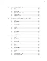
Major Component List......................................................................................................2-1
ALI M1521 ......................................................................................................................2-2
Features............................................................................................................2-2
Block Diagram .................................................................................................2-4
System Architecture .........................................................................................2-5
Data Path .........................................................................................................2-6
Pin Diagram .....................................................................................................2-7
Signal Descriptions ..........................................................................................2-8
ALI M1523 ....................................................................................................................2-14
Features..........................................................................................................2-14
Block Diagram ...............................................................................................2-16
Pin Diagram ...................................................................................................2-17
Signal Descriptions ........................................................................................2-18
Содержание Extensa 61X
Страница 1: ...TI Extensa 61X Series AcerNote 370P Notebook Service Guide PART NO 2238309 0809 DOC NO PRINTED IN USA ...
Страница 6: ...vi ...
Страница 26: ...1 8 Service Guide Figure 1 5 Main Board Layout Bottom Side ...
Страница 49: ...System Introduction 1 31 1 5 1 3 Power Management Figure 1 14 Power Management Block Diagram ...
Страница 55: ...System Introduction 1 37 1 6 System Block Diagram Figure 1 15 System Block Diagram ...
Страница 64: ...Major Chips Description 2 7 2 2 5 Pin Diagram Figure 2 4 M1521 Pin Diagram ...
Страница 99: ...2 42 Service Guide 2 5 3 Pin Diagram Figure 2 10 C T 65550 Pin Diagram ...
Страница 116: ...Major Chips Description 2 59 2 6 4 Block Diagram Figure 2 11 Functional Block Diagram 16 bit PC Card Interface ...
Страница 117: ...2 60 Service Guide Figure 2 12 Functional block diagram CardBus Card Interface ...
Страница 118: ...Major Chips Description 2 61 2 6 5 Pin Diagram Figure 2 13 PCI to PC Card 16 bit terminal assignments ...
Страница 119: ...2 62 Service Guide Figure 2 14 PCI to CardBus terminal assignments ...
Страница 135: ...2 78 Service Guide 2 7 3 Pin Diagram Figure 2 16 NS87336VJG Pin Diagram ...
Страница 145: ...2 88 Service Guide 2 8 2 Pin Diagram Figure 2 17 YMF715 Block Diagram ...
Страница 185: ...Disassembly and Unit Replacement 4 5 Figure 4 3 Disassembly Sequence Flowchart ...
Страница 209: ...B 2 Service Guide ...
Страница 210: ...Exploded View Diagram B 3 ...
Страница 217: ...A p p e n d i x D A p p e n d i x D Schematics This appendix shows the schematic diagrams of the notebook ...


