xvi
List of Tables
Port Descriptions .............................................................................................................1-3
Indicator Status Descriptions ............................................................................................1-4
System Specifications .......................................................................................................1-5
System Specifications (continued).....................................................................................1-6
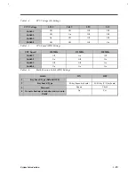
CPU Voltage (S1) Settings..............................................................................................1-13
.............................................................................................1-13
Multi-Function Switch (SW2) Settings ...........................................................................1-13
Memory Address Map ....................................................................................................1-14
Interrupt Channel Map ...................................................................................................1-14
DMA Channel Map ........................................................................................................1-15
I/O Address Map ............................................................................................................1-15
M7101 GPIO Port Definition..........................................................................................1-16
Processor Specifications..................................................................................................1-16
BIOS Specifications........................................................................................................1-17
Memory Configurations..................................................................................................1-18
Video RAM Configuration .............................................................................................1-19
Video Hardware Specification.........................................................................................1-19
Supported External CRT Resolutions..............................................................................1-19
Supported LCD Resolutions............................................................................................1-20
Parallel Port Configurations............................................................................................1-21
Serial Port Configurations ..............................................................................................1-21
Audio Specifications.......................................................................................................1-22
PCMCIA Specifications..................................................................................................1-22
Touchpad Specifications .................................................................................................1-23
Keyboard Specifications..................................................................................................1-23
Windows 95 Key Descriptions ........................................................................................1-23
FDD Specifications.........................................................................................................1-24
HDD Specifications ........................................................................................................1-24
Содержание Extensa 61X
Страница 1: ...TI Extensa 61X Series AcerNote 370P Notebook Service Guide PART NO 2238309 0809 DOC NO PRINTED IN USA ...
Страница 6: ...vi ...
Страница 26: ...1 8 Service Guide Figure 1 5 Main Board Layout Bottom Side ...
Страница 49: ...System Introduction 1 31 1 5 1 3 Power Management Figure 1 14 Power Management Block Diagram ...
Страница 55: ...System Introduction 1 37 1 6 System Block Diagram Figure 1 15 System Block Diagram ...
Страница 64: ...Major Chips Description 2 7 2 2 5 Pin Diagram Figure 2 4 M1521 Pin Diagram ...
Страница 99: ...2 42 Service Guide 2 5 3 Pin Diagram Figure 2 10 C T 65550 Pin Diagram ...
Страница 116: ...Major Chips Description 2 59 2 6 4 Block Diagram Figure 2 11 Functional Block Diagram 16 bit PC Card Interface ...
Страница 117: ...2 60 Service Guide Figure 2 12 Functional block diagram CardBus Card Interface ...
Страница 118: ...Major Chips Description 2 61 2 6 5 Pin Diagram Figure 2 13 PCI to PC Card 16 bit terminal assignments ...
Страница 119: ...2 62 Service Guide Figure 2 14 PCI to CardBus terminal assignments ...
Страница 135: ...2 78 Service Guide 2 7 3 Pin Diagram Figure 2 16 NS87336VJG Pin Diagram ...
Страница 145: ...2 88 Service Guide 2 8 2 Pin Diagram Figure 2 17 YMF715 Block Diagram ...
Страница 185: ...Disassembly and Unit Replacement 4 5 Figure 4 3 Disassembly Sequence Flowchart ...
Страница 209: ...B 2 Service Guide ...
Страница 210: ...Exploded View Diagram B 3 ...
Страница 217: ...A p p e n d i x D A p p e n d i x D Schematics This appendix shows the schematic diagrams of the notebook ...

