2-16
Service Guide
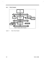
2.3.2
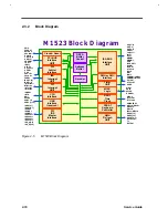
Block Diagram
M 1 5 2 3 Blo c k Diagram
DATA
Buffer
Control
Address
Buffer
Decoder
Clock & Reset
PCI BUS
Interface
UNIT
PCI
Arbiter
Interface
ISA
Interrupt
UNIT
PCI
Interrupt
UNIT
CPU
Interface
USB
Interface
(reserved)
PCI
IDE
Master
Interface
ISA BUS
Interface
UNIT
DMA
Refresh
UNIT
PMU or APIC
Interface
PS2/AT
Keyboard
Controller
Timer
UNIT
MISC.
Logic
REAL
Time
Clock
PWG
CPURST
RSTDRV
OSC14M
PCICLK
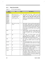
CBEJ[3:0]
AD[31:0]
FRAMEJ
TRDYJ
IRDYJ
STOPJ
DEVSELJ
SERRJ
PAR
PHOLDJ
PHLDAJ
FERRJ
IRQ[15:14]
IRQ[11:3]
INTAJ/M1II
NTBJ/S0
INTCJ/S1
INTDJ/S2
IGNNEJ
INTR
NMI
A20MJ
USBCLK
USBP[11:10]
IDRQ[0:1]
IDAKJ[0:1]
IDERDY
IDEIORJ
IDEIOWJ
IDESCS3J
IDESCS1J
IDEPCS3J
IDEPCS1J
IDE_A[2:0]
IDE_D[15:0]
SD[15:8]
XD[7:0]
SA[19:0]
SBHEJ
LA[23:17]
IO16J
M16J
MEMRJ
MEMWJ
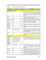
AEN
IOCHRDYJ
NOWSJ
IOCHKJ
SYSCLK
BALE
IORJ
IOWJ
SMEMRJ/LMEGJ
SMEMWJ/RTCAS
EXTSW
STPCLKJ
SPKR
SIRQI
XDIR
SPLED
ROMCSJ
SIRQII
RTC32KI
RTC32KII
KBINH/IRQ1
KBCLK/KBCSJ
KBDATA
MSCLK
IRQ12/MDATA
DREQ[7:5]
DREQ[3:0]
DACKJ[7:5]
DACK2J/3J
TC
REFSHJ
Figure 2-5
M1523 Block Diagram
Содержание Extensa 61X
Страница 1: ...TI Extensa 61X Series AcerNote 370P Notebook Service Guide PART NO 2238309 0809 DOC NO PRINTED IN USA ...
Страница 6: ...vi ...
Страница 26: ...1 8 Service Guide Figure 1 5 Main Board Layout Bottom Side ...
Страница 49: ...System Introduction 1 31 1 5 1 3 Power Management Figure 1 14 Power Management Block Diagram ...
Страница 55: ...System Introduction 1 37 1 6 System Block Diagram Figure 1 15 System Block Diagram ...
Страница 64: ...Major Chips Description 2 7 2 2 5 Pin Diagram Figure 2 4 M1521 Pin Diagram ...
Страница 99: ...2 42 Service Guide 2 5 3 Pin Diagram Figure 2 10 C T 65550 Pin Diagram ...
Страница 116: ...Major Chips Description 2 59 2 6 4 Block Diagram Figure 2 11 Functional Block Diagram 16 bit PC Card Interface ...
Страница 117: ...2 60 Service Guide Figure 2 12 Functional block diagram CardBus Card Interface ...
Страница 118: ...Major Chips Description 2 61 2 6 5 Pin Diagram Figure 2 13 PCI to PC Card 16 bit terminal assignments ...
Страница 119: ...2 62 Service Guide Figure 2 14 PCI to CardBus terminal assignments ...
Страница 135: ...2 78 Service Guide 2 7 3 Pin Diagram Figure 2 16 NS87336VJG Pin Diagram ...
Страница 145: ...2 88 Service Guide 2 8 2 Pin Diagram Figure 2 17 YMF715 Block Diagram ...
Страница 185: ...Disassembly and Unit Replacement 4 5 Figure 4 3 Disassembly Sequence Flowchart ...
Страница 209: ...B 2 Service Guide ...
Страница 210: ...Exploded View Diagram B 3 ...
Страница 217: ...A p p e n d i x D A p p e n d i x D Schematics This appendix shows the schematic diagrams of the notebook ...


