1-
28
Service Guide
1.4.25
LCD
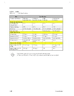
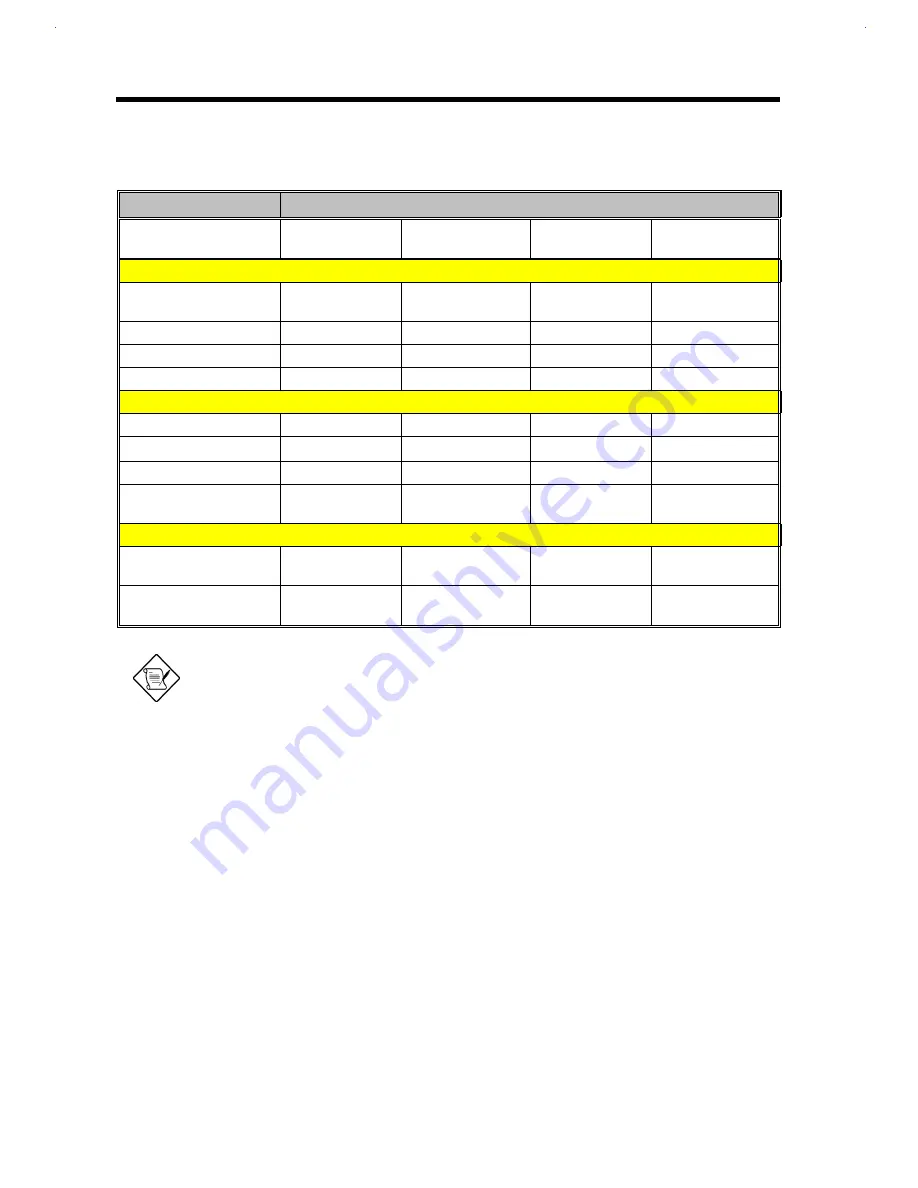
Table 1-33
LCD Specifications
Item
Specification
Vendor & model name
HITACHI
LMG9900ZWCC
TORiSAN
LM-FH53-22NAW
IBM
ITSV45E
GOLDSTAR
LP121S1-J
Mechanical Specifications
LCD display area
(diagonal, inch)
11.3
11.3
11.3
12.1
Display technology
STN
STN
TFT
TFT
Resolution
SVGA (800x600)
VGA (800x600)
SVGA (800x600)
SVGA (800x600)
Supported colors
--
--
262,144 colors
262,144 colors
Optical Specification
Contrast ratio
30 (typ.)
30 (typ.)
100 (typ.)
100 (typ.)
Brightness (cd/m
2
)
70 (typ.)
70 (typ.)
70 (typ.)
70 (typ.)
Brightness control
keyboard hotkey
keyboard hotkey
keyboard hotkey
keyboard hotkey
Contrast control
using keyboard
hotkey
using keyboard
hotkey
none
none
Electrical Specification
Supply voltage for LCD
display
3.3 or 5 (typ.)
3.3 (typ.)
3.3
3.3 (typ.), 3.63
(max.)
Supply voltage for LCD
backlight (Vrms)
590 (typ.)
590 (typ.)
590
480
The LCD ID code can be set by using the LCD ID utilization utility
(370pw.exe/370pr.exe). Please refer to the software specification section for details.
Содержание Extensa 61X
Страница 1: ...TI Extensa 61X Series AcerNote 370P Notebook Service Guide PART NO 2238309 0809 DOC NO PRINTED IN USA ...
Страница 6: ...vi ...
Страница 26: ...1 8 Service Guide Figure 1 5 Main Board Layout Bottom Side ...
Страница 49: ...System Introduction 1 31 1 5 1 3 Power Management Figure 1 14 Power Management Block Diagram ...
Страница 55: ...System Introduction 1 37 1 6 System Block Diagram Figure 1 15 System Block Diagram ...
Страница 64: ...Major Chips Description 2 7 2 2 5 Pin Diagram Figure 2 4 M1521 Pin Diagram ...
Страница 99: ...2 42 Service Guide 2 5 3 Pin Diagram Figure 2 10 C T 65550 Pin Diagram ...
Страница 116: ...Major Chips Description 2 59 2 6 4 Block Diagram Figure 2 11 Functional Block Diagram 16 bit PC Card Interface ...
Страница 117: ...2 60 Service Guide Figure 2 12 Functional block diagram CardBus Card Interface ...
Страница 118: ...Major Chips Description 2 61 2 6 5 Pin Diagram Figure 2 13 PCI to PC Card 16 bit terminal assignments ...
Страница 119: ...2 62 Service Guide Figure 2 14 PCI to CardBus terminal assignments ...
Страница 135: ...2 78 Service Guide 2 7 3 Pin Diagram Figure 2 16 NS87336VJG Pin Diagram ...
Страница 145: ...2 88 Service Guide 2 8 2 Pin Diagram Figure 2 17 YMF715 Block Diagram ...
Страница 185: ...Disassembly and Unit Replacement 4 5 Figure 4 3 Disassembly Sequence Flowchart ...
Страница 209: ...B 2 Service Guide ...
Страница 210: ...Exploded View Diagram B 3 ...
Страница 217: ...A p p e n d i x D A p p e n d i x D Schematics This appendix shows the schematic diagrams of the notebook ...


