Date:
February 12, 1997
Sheet
19
of
25
Size
Document Number
REV
A3
96149
SC
Title
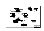
370P/J (CRT CONN.& ZV PORT)
TAIPEI TAIWAN R.O.C
ACER
ZV_PCLK
ZV_VREF
A_WP
UV7
A_A25
A_A10
A_A11
21
17
17
VCC
24
B0
2
A0
3
A1
4
B1
5
B2
6
A2
7
A3
8
B3
9
B4
10
A4
11
OEA
1
OEB
13
GND
12
B9
23
A9
22
A8
21
B8
20
B7
19
A7
18
A6
17
B6
16
B5
15
A5
14
U9
QQST3384
VCC
24
B0
2
A0
3
A1
4
B1
5
B2
6
A2
7
A3
8
B3
9
B4
10
A4
11
OEA
1
OEB
13
GND
12
B9
23
A9
22
A8
21
B8
20
B7
19
A7
18
A6
17
B6
16
B5
15
A5
14
U14
QQST3384
1
2
D6
PRLL4001
A_A[0..25]
Y[0..7]
UV[0..7]
Y2
UV0
UV1
UV2
UV4
UV6
A_A15
A_A16
A_A17
A_A21
A_A22
A_A8
A_A12
+5V
15,21,22
17
17
1
2
R69
4K7R3
C72
SCD1U
PLFS
Y5
Y6
Y7
A_A14
A_A19
A_A20
R3
R4
R7
R0
20
1
2
3
4
5
6
7
8
9
10
11
12
13
14
15
16
17
18
19
20
21
22
23
24
25
26
27
28
29
30
31
32
33
34
35
36
37
38
39
40
80
79
78
77
76
75
74
73
72
71
70
69
68
67
66
65
64
63
62
61
60
59
58
57
56
55
54
53
52
51
50
49
48
47
46
45
44
43
42
41
CN6
JAE-CONN80C
R[0..7]
SUD[0..7]
PSHFCLK
PLP
R1
R2
R5
17
17
20
20
1
3
2
L13
ELKE101FA
C159
SCD1U
1
2
R126
470R3
1
2
R15
330R3
1
2
L12
MLB321611
UD1
LD2
UD2
ID_CLK
BLVR#
ID_DATA
CCFT_ON
BBT_QCHG
PLED#
R6
SUD2
SUD1
SUD6
SUD5
+5V
CCFTPWR
+5V
8
8
8
8
17
17
17
20
16
C171
SC1U25V5MY
C1
SCD1U
UD3
UD0
LD3
LD1
LD0
LCD_DISPLAY
ENAVEE
VEEVR#
PMOD
Y3
Y4
A_A13
A_A18
SUD3
SUD0
SUD7
SUD4
LCDVEE
LCDVEE
LCD+5V
17
8
17
17
17
17
17
20
20
1
2
R3
10KR3
1
2
R36
10KR3
Y0
Y1
UV3
UV5
A_A23
A_A24
A_A9
+5V
+5V
ZV_HREF
CCINTR
$CPUINTR
1
8
17
16
17
5
10
14
3
8
12
1
6
15
4
9
13
2
7
11
CN2
VIDEO-15-4-D
1
2
R118
1KR3
1
2
R125
1KR3
1
2
R2
100R3
1
2
R34
33R3
VSW1
VSW3
DDC_CLK
DDC_DATA
CRT_R
CRT_G
CRT_B
CRT_HS
CRT_VS
CRT_VS
CRT_B
CRT_HS
CRT_G
CRT_R
8
17
20
20
20
20
20
VR_U/D#
8
TPX4
TP-1
THIS CONN. IS LCD INTERFACE CONN.
C3
SC1U25V5MY
C4
SCD1U
8
Содержание Extensa 61X
Страница 1: ...TI Extensa 61X Series AcerNote 370P Notebook Service Guide PART NO 2238309 0809 DOC NO PRINTED IN USA ...
Страница 6: ...vi ...
Страница 26: ...1 8 Service Guide Figure 1 5 Main Board Layout Bottom Side ...
Страница 49: ...System Introduction 1 31 1 5 1 3 Power Management Figure 1 14 Power Management Block Diagram ...
Страница 55: ...System Introduction 1 37 1 6 System Block Diagram Figure 1 15 System Block Diagram ...
Страница 64: ...Major Chips Description 2 7 2 2 5 Pin Diagram Figure 2 4 M1521 Pin Diagram ...
Страница 99: ...2 42 Service Guide 2 5 3 Pin Diagram Figure 2 10 C T 65550 Pin Diagram ...
Страница 116: ...Major Chips Description 2 59 2 6 4 Block Diagram Figure 2 11 Functional Block Diagram 16 bit PC Card Interface ...
Страница 117: ...2 60 Service Guide Figure 2 12 Functional block diagram CardBus Card Interface ...
Страница 118: ...Major Chips Description 2 61 2 6 5 Pin Diagram Figure 2 13 PCI to PC Card 16 bit terminal assignments ...
Страница 119: ...2 62 Service Guide Figure 2 14 PCI to CardBus terminal assignments ...
Страница 135: ...2 78 Service Guide 2 7 3 Pin Diagram Figure 2 16 NS87336VJG Pin Diagram ...
Страница 145: ...2 88 Service Guide 2 8 2 Pin Diagram Figure 2 17 YMF715 Block Diagram ...
Страница 185: ...Disassembly and Unit Replacement 4 5 Figure 4 3 Disassembly Sequence Flowchart ...
Страница 209: ...B 2 Service Guide ...
Страница 210: ...Exploded View Diagram B 3 ...
Страница 217: ...A p p e n d i x D A p p e n d i x D Schematics This appendix shows the schematic diagrams of the notebook ...


