BIOS Setup Information
3-15
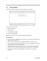
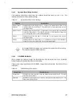
Table 3-6
System Status Descriptions
Item
Description
CPU ID
Shows the processor type
CPU Clock
Shows the processor speed
System memory
Shows the total system memory
Video memory
Shows the total video memory
Floppy Disk A
Shows the floppy drive A type
Security
Shows floppy drive A security setting
Floppy Disk B
Shows the floppy drive B type
Security
Shows floppy drive B security setting
Hard Disk
Shows the IDE drive type and size and its security setting
Security
Shows hard disk drive security setting
CD ROM
Shows the presence of a CD-ROM drive
System Boot Drive
Shows the boot sequence setting
CD ROM Bootable
Shows if the CD ROM Bootable feature is enabled or not
Serial Port 1
Shows the serial port base address and IRQ
Parallel Port
Shows the parallel port base address and IRQ
Operation Mode
Shows the parallel port operation mode
Internal Cache
Shows the internal cache size and setting
External Cache
Shows the external cache size
Pointing Device
Shows the presence of a pointing device
Internal KB
Shows the internal keyboard type
This screen may show other items which are not in this list if certain parameters
settings are changed and enabled.
Содержание Extensa 61X
Страница 1: ...TI Extensa 61X Series AcerNote 370P Notebook Service Guide PART NO 2238309 0809 DOC NO PRINTED IN USA ...
Страница 6: ...vi ...
Страница 26: ...1 8 Service Guide Figure 1 5 Main Board Layout Bottom Side ...
Страница 49: ...System Introduction 1 31 1 5 1 3 Power Management Figure 1 14 Power Management Block Diagram ...
Страница 55: ...System Introduction 1 37 1 6 System Block Diagram Figure 1 15 System Block Diagram ...
Страница 64: ...Major Chips Description 2 7 2 2 5 Pin Diagram Figure 2 4 M1521 Pin Diagram ...
Страница 99: ...2 42 Service Guide 2 5 3 Pin Diagram Figure 2 10 C T 65550 Pin Diagram ...
Страница 116: ...Major Chips Description 2 59 2 6 4 Block Diagram Figure 2 11 Functional Block Diagram 16 bit PC Card Interface ...
Страница 117: ...2 60 Service Guide Figure 2 12 Functional block diagram CardBus Card Interface ...
Страница 118: ...Major Chips Description 2 61 2 6 5 Pin Diagram Figure 2 13 PCI to PC Card 16 bit terminal assignments ...
Страница 119: ...2 62 Service Guide Figure 2 14 PCI to CardBus terminal assignments ...
Страница 135: ...2 78 Service Guide 2 7 3 Pin Diagram Figure 2 16 NS87336VJG Pin Diagram ...
Страница 145: ...2 88 Service Guide 2 8 2 Pin Diagram Figure 2 17 YMF715 Block Diagram ...
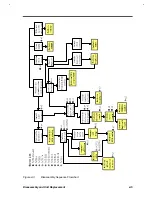
Страница 185: ...Disassembly and Unit Replacement 4 5 Figure 4 3 Disassembly Sequence Flowchart ...
Страница 209: ...B 2 Service Guide ...
Страница 210: ...Exploded View Diagram B 3 ...
Страница 217: ...A p p e n d i x D A p p e n d i x D Schematics This appendix shows the schematic diagrams of the notebook ...


