1-
12
Service Guide
1.3
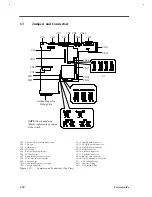
Jumpers and Connectors
CN1
CN6
CN2
CN7
CN3
CN8 CN9
CN4
CN10
CN5
CN11
CN12
CN14
CN17
CN18
CN19
SW2
SW3
CN13
CN15
CN16
S1
CN1 External PS/2 keyboard/mouse port
CN12 Audio Board Connector
CN2 VGA port
CN13 PCMCIA socket connector
CN3 Parallel port
CN14 Diskette Drive connector
CN4 Serial port
CN15 HDD Connector
CN5 External floppy drive port
CN16 Keyboard connector
CN6 LCD Connector
CN17 CD-ROM connector
CN7 Audio speaker connector (left)
CN18 Battery pack connector
CN8 LCD cover switch connector
CN19 Track Point Board Connector
CN9 Fan connector
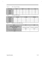
S1 CPU Voltage Setting
CN10 Audio speaker connector (right)
SW2
Function Setting
CN11 Charger Connector
SW3
CPU Speed Setting
Figure 1-13
Jumpers and Connectors (Top View)
Golden Finger for
Debug Card
NOTE: The shaded area
(Black) indicates the position
of the switch.
Содержание Extensa 61X
Страница 1: ...TI Extensa 61X Series AcerNote 370P Notebook Service Guide PART NO 2238309 0809 DOC NO PRINTED IN USA ...
Страница 6: ...vi ...
Страница 26: ...1 8 Service Guide Figure 1 5 Main Board Layout Bottom Side ...
Страница 49: ...System Introduction 1 31 1 5 1 3 Power Management Figure 1 14 Power Management Block Diagram ...
Страница 55: ...System Introduction 1 37 1 6 System Block Diagram Figure 1 15 System Block Diagram ...
Страница 64: ...Major Chips Description 2 7 2 2 5 Pin Diagram Figure 2 4 M1521 Pin Diagram ...
Страница 99: ...2 42 Service Guide 2 5 3 Pin Diagram Figure 2 10 C T 65550 Pin Diagram ...
Страница 116: ...Major Chips Description 2 59 2 6 4 Block Diagram Figure 2 11 Functional Block Diagram 16 bit PC Card Interface ...
Страница 117: ...2 60 Service Guide Figure 2 12 Functional block diagram CardBus Card Interface ...
Страница 118: ...Major Chips Description 2 61 2 6 5 Pin Diagram Figure 2 13 PCI to PC Card 16 bit terminal assignments ...
Страница 119: ...2 62 Service Guide Figure 2 14 PCI to CardBus terminal assignments ...
Страница 135: ...2 78 Service Guide 2 7 3 Pin Diagram Figure 2 16 NS87336VJG Pin Diagram ...
Страница 145: ...2 88 Service Guide 2 8 2 Pin Diagram Figure 2 17 YMF715 Block Diagram ...
Страница 185: ...Disassembly and Unit Replacement 4 5 Figure 4 3 Disassembly Sequence Flowchart ...
Страница 209: ...B 2 Service Guide ...
Страница 210: ...Exploded View Diagram B 3 ...
Страница 217: ...A p p e n d i x D A p p e n d i x D Schematics This appendix shows the schematic diagrams of the notebook ...

