1-
34
Service Guide
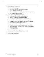
Table 1-37
Hibernation Mode Conditions and Descriptions
Condition
Description
The condition to enter
Hibernation Mode
•
“Hard Disk Drive” is not [Disabled] in System Security of BIOS SETUP.
•
“Hard Disk 0” is not [None] in Basic System Configuration of BIOS SETUP.
•
HDD has already located enough free contiguous disk space generated by the
Sleep Manager and this free space is not corrupted.
•
Standby/Hibernation Timer times-out or Standby/Hibernation Hotkey pressed and
there is no activity within 1/2 second.
The condition of
Hibernation Mode
•
Except the RTC, 6375 (state machine), KB controller and power switch, all the
system components are off.
The condition back to On
Mode
•
Turn off then on the system.
DISPLAY STANDBY MODE
Screen activity is determined by the keyboard, the built-in touchpad, and an external PS/2 pointing device.
If these devices are idle for the period specified by the Display Standby Timer, the display shuts off until you
press a key or move the touchpad or external mouse.
Table 1-38
Display Standby Mode Conditions and Descriptions
Condition
Description
The condition to enter
Display Standby Mode
•
Pointing device is idle until Display Standby Timer times-out or LCD cover is
closed.
The condition of Display
Standby Mode
•
All the system components are on except LCD backlight and CRT horizontal
frequency output (if CRT is connected)
The condition back to On
Mode
•
Any keystroke (Internal KB or External KB)
•
Pointing device activity
The VGA BIOS should support DPMS (Desktop Power Management System) for the standby
and hibernation mode function call. When the Display Standby Timer expires, the system
BIOS will execute the DPMS service routines.
HARD DISK STANDBY MODE
The hard disk enters standby mode when there are no disk read/write operations within the period of time
specified by the Hard Disk Standby Timer. In the standby state, the power supplied to the hard disk is
reduced to a minimum. The hard disk returns to normal once the system accesses it.
Содержание Extensa 61X
Страница 1: ...TI Extensa 61X Series AcerNote 370P Notebook Service Guide PART NO 2238309 0809 DOC NO PRINTED IN USA ...
Страница 6: ...vi ...
Страница 26: ...1 8 Service Guide Figure 1 5 Main Board Layout Bottom Side ...
Страница 49: ...System Introduction 1 31 1 5 1 3 Power Management Figure 1 14 Power Management Block Diagram ...
Страница 55: ...System Introduction 1 37 1 6 System Block Diagram Figure 1 15 System Block Diagram ...
Страница 64: ...Major Chips Description 2 7 2 2 5 Pin Diagram Figure 2 4 M1521 Pin Diagram ...
Страница 99: ...2 42 Service Guide 2 5 3 Pin Diagram Figure 2 10 C T 65550 Pin Diagram ...
Страница 116: ...Major Chips Description 2 59 2 6 4 Block Diagram Figure 2 11 Functional Block Diagram 16 bit PC Card Interface ...
Страница 117: ...2 60 Service Guide Figure 2 12 Functional block diagram CardBus Card Interface ...
Страница 118: ...Major Chips Description 2 61 2 6 5 Pin Diagram Figure 2 13 PCI to PC Card 16 bit terminal assignments ...
Страница 119: ...2 62 Service Guide Figure 2 14 PCI to CardBus terminal assignments ...
Страница 135: ...2 78 Service Guide 2 7 3 Pin Diagram Figure 2 16 NS87336VJG Pin Diagram ...
Страница 145: ...2 88 Service Guide 2 8 2 Pin Diagram Figure 2 17 YMF715 Block Diagram ...
Страница 185: ...Disassembly and Unit Replacement 4 5 Figure 4 3 Disassembly Sequence Flowchart ...
Страница 209: ...B 2 Service Guide ...
Страница 210: ...Exploded View Diagram B 3 ...
Страница 217: ...A p p e n d i x D A p p e n d i x D Schematics This appendix shows the schematic diagrams of the notebook ...


