Major Chips Description
2-87
2.8
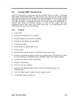
Yamaha YMF715 Audio Chip
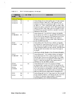
YMF715-S (OPL3-SA3) is a single audio chip that integrates OPL3 and its DAC, 16 bit Sigma-
delta CODEC, MPU401 MIDI interface, joystick with timer, and a 3D enhanced controller including
all the analog components which is suitable for multi-media application. This LSI is fully compliant
with Plug and Play ISA 1.0a, and supports all the necessary features, i.e. 16 bit address decode,
more IRQs and DMAs in compliance with PC'96. This LSI also supports the expandability, i.e.
Zoomed Video, Modem and CD-ROM interface in a Plug and Play manner, and power
management (power down, power save, partial power down, and suspend/resume) that is
indispensable with power-conscious application.
2.8.1
Features
•
Built-in OPL3
•
Supports Sound Blaster Game compatibility
•
Supports Windows Sound System compatibility
•
Supports Plug
&
Play ISA 1.0a compatibility
•
Full Duplex operation
•
Built-in MPU401 Compatible MIDI I/O port
•
Built-in Joystick
•
Built-in the 3D enhanced controller including all the analog components
•
Supports multi-purpose pin function (Support 16-bit address decode, DAC interface for OPL4-
ML, Zoomed Video port, EEPROM interface, MODEM interface, IDE CD-ROM interface)
•
Hardware and software master volume control
•
Supports monaural input
•
24 mA 1TL bus drive capability
•
Supports Power Management(power down, power save, partial power down, and
suspend/resume)
..
•
+5V/ +3.3V power supply for digital, 5V power supply for analog.
•
100 pin SQFP package (YMF715-S)
Содержание Extensa 61X
Страница 1: ...TI Extensa 61X Series AcerNote 370P Notebook Service Guide PART NO 2238309 0809 DOC NO PRINTED IN USA ...
Страница 6: ...vi ...
Страница 26: ...1 8 Service Guide Figure 1 5 Main Board Layout Bottom Side ...
Страница 49: ...System Introduction 1 31 1 5 1 3 Power Management Figure 1 14 Power Management Block Diagram ...
Страница 55: ...System Introduction 1 37 1 6 System Block Diagram Figure 1 15 System Block Diagram ...
Страница 64: ...Major Chips Description 2 7 2 2 5 Pin Diagram Figure 2 4 M1521 Pin Diagram ...
Страница 99: ...2 42 Service Guide 2 5 3 Pin Diagram Figure 2 10 C T 65550 Pin Diagram ...
Страница 116: ...Major Chips Description 2 59 2 6 4 Block Diagram Figure 2 11 Functional Block Diagram 16 bit PC Card Interface ...
Страница 117: ...2 60 Service Guide Figure 2 12 Functional block diagram CardBus Card Interface ...
Страница 118: ...Major Chips Description 2 61 2 6 5 Pin Diagram Figure 2 13 PCI to PC Card 16 bit terminal assignments ...
Страница 119: ...2 62 Service Guide Figure 2 14 PCI to CardBus terminal assignments ...
Страница 135: ...2 78 Service Guide 2 7 3 Pin Diagram Figure 2 16 NS87336VJG Pin Diagram ...
Страница 145: ...2 88 Service Guide 2 8 2 Pin Diagram Figure 2 17 YMF715 Block Diagram ...
Страница 185: ...Disassembly and Unit Replacement 4 5 Figure 4 3 Disassembly Sequence Flowchart ...
Страница 209: ...B 2 Service Guide ...
Страница 210: ...Exploded View Diagram B 3 ...
Страница 217: ...A p p e n d i x D A p p e n d i x D Schematics This appendix shows the schematic diagrams of the notebook ...

