Spare Parts
C-
3
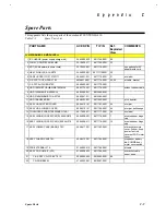
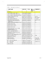
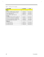
Table C1 Spare parts list (continued)
PART NAME
ACER P/N
TI P/N
Ref.
Exploded
View
COMMENTS
<< MAIN BD >>
1 IC CPU INTEL P54CSLM 120M 3.1V
01.IP54S.C0M
9811798-0001
2 IC CPU INTEL P54CSLM 150M 2.9V SPGA
01.IP54S.F0B
9815594-0001
3 IC CPU INTEL P55C (MMX) 150M 2.45V SPGA
01.ip55c.f00
9815595-0001
4 MAIN BOARD 0MB W/O CPU 370P
55.48401.001
9811800-0001
w/o CPU
5 AUDIO BOARD 370P
6M.48417.001
9811801-0001 31
audio bd & cable
6 HDD TRANSFER BOARD 370P
55.48403.001
9811802-0001 43
w/ connector
7 KEYBOARD TRANSFER BOARD 370P
55.48404.001
9811803-0001
w/connector, mylar
8 CMOS BATTERY ASSY. (ASSY RTC BTY
MODULE 370P)
60.48416.001
9811804-0001
BT1
9 (BIOS IC) IC MASKROM M38802M2-013HP 64P
85.45001.001
9811807-0001
U16
10 LOGO PLATE, EXT 610
40.46813.041
9811819-0001
11 LOGO PLATE, EXT 610CD
40.46813.051
9811820-0001
12 LOGO PLATE, EXT 610CDT
40.46813.061
9811821-0001
13 LOGO PLATE, EXT 616
40.46813.101
9815703-0001
14 CLOSE COVER SWITCH (W.A. 2P 50MM
W/CVR SW,EXT 61X)
50.46911.021
9811822-0001
15 KNOB TH (MOUSE BUTTONS)
42.46912.001
9811823-0001 23
16 COVER, SIMM MEMORY,EXT 61X
34.46904.001
9815575-0001 87
17 CABLE ASSY, TOUCHPAD-FPC,EXT 61X
50.48401.001
9815577-0001
18 HDD DOOR, EXT 61X
42.46905.002
9815578-0001
19 EXT FDD COVER (RUBBER DOOR), EXT 61X
47.46903.001
9815580-0001 67
20 I/O DOOR (REAR), EXT 61X
6M.48416.001
9815581-0001 78, 79
w/latch
21 SPEAKER 0.3W T023S03
23.40015.021
9815596-0001 41
22 BATTERY BOARD
55.46904.001
9815597-0001
w/ assy. cable
23 ASSY FDD INTERNAL
91.46905.011
9811787-0001 62
w/ bracket, cable,
bezel, knob, lens
24 FDD 1.44 3.5" D353F2 MIT
see above kit
see above kit
25 ASSY FDD BZL
see above kit
see above kit
67
with bezel & lens
26 FDD CABLE
50.46902.001
9815426-0001 63
27 BATTERY DOOR
42.46955.001
9815598-0001 29
Содержание Extensa 61X
Страница 1: ...TI Extensa 61X Series AcerNote 370P Notebook Service Guide PART NO 2238309 0809 DOC NO PRINTED IN USA ...
Страница 6: ...vi ...
Страница 26: ...1 8 Service Guide Figure 1 5 Main Board Layout Bottom Side ...
Страница 49: ...System Introduction 1 31 1 5 1 3 Power Management Figure 1 14 Power Management Block Diagram ...
Страница 55: ...System Introduction 1 37 1 6 System Block Diagram Figure 1 15 System Block Diagram ...
Страница 64: ...Major Chips Description 2 7 2 2 5 Pin Diagram Figure 2 4 M1521 Pin Diagram ...
Страница 99: ...2 42 Service Guide 2 5 3 Pin Diagram Figure 2 10 C T 65550 Pin Diagram ...
Страница 116: ...Major Chips Description 2 59 2 6 4 Block Diagram Figure 2 11 Functional Block Diagram 16 bit PC Card Interface ...
Страница 117: ...2 60 Service Guide Figure 2 12 Functional block diagram CardBus Card Interface ...
Страница 118: ...Major Chips Description 2 61 2 6 5 Pin Diagram Figure 2 13 PCI to PC Card 16 bit terminal assignments ...
Страница 119: ...2 62 Service Guide Figure 2 14 PCI to CardBus terminal assignments ...
Страница 135: ...2 78 Service Guide 2 7 3 Pin Diagram Figure 2 16 NS87336VJG Pin Diagram ...
Страница 145: ...2 88 Service Guide 2 8 2 Pin Diagram Figure 2 17 YMF715 Block Diagram ...
Страница 185: ...Disassembly and Unit Replacement 4 5 Figure 4 3 Disassembly Sequence Flowchart ...
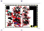
Страница 209: ...B 2 Service Guide ...
Страница 210: ...Exploded View Diagram B 3 ...
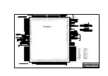
Страница 217: ...A p p e n d i x D A p p e n d i x D Schematics This appendix shows the schematic diagrams of the notebook ...

