


TPU2000/2000R Modbus/Modbus Plus Automation Guide
73
One must take particular note when interpreting the data bits returned from the IED. Different manufacturers input
data from Modbus devices however, each manufacturer starts its address start addresses taking into account the
zero offset whereas, other manufacturers do not. Some manufacturers number their data bit presentations in the
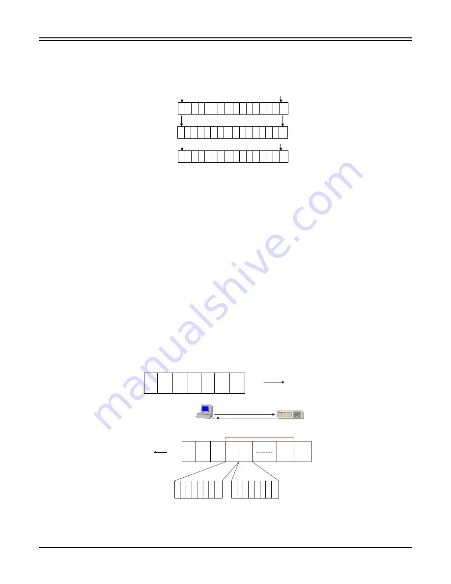
registers differently. Figure 5-23 below illustrates the register decoding differences.
ABB
DOCUMENTATION
Most Significant Bit Least Significant Bit
15 1413 12 11 10 9 8 7 6 5 4 3 2 1 0
- First data Address = 1.
MODICON
DOCUMENTATION
1 2 3 4 5 6 7 8 9 1011 1213 1415 16
- First data Address = 1.
TELEMECANIQUE
DOCUMENTATION
15 1413 12 11 10 9 8 7 6 5 4 3 2 1 0
- First data Address = 0.
For Example: If a Telemechanique PLC was serving as a Modbus host, the ABB
documentation for bit interpretation most significant bit = bit 15 leftmost bit, least
significant bit = bit 0 rightmost bit. However, to access a register the host would need
to subtract the value of 1 from the data address to obtain the correct data.
If a Modicon PLC was serving as a Modbus host, the ABB documentation would need
to be transposed to acknowledge that any data analyzed by the host in the bit 16 position
would reflect the status described as Bit 0 lsb nomenclature. No data address offset
would need to be performed to obtain the correct information from the protective relay.
Figure 5-23. Vendor Documentation Translation Example
Function Code 03 – Read Holding Registers (Read Only)
The 4x frame sequence is illustrated in Figure 5-24 for Function 03 (Read Holding Registers). The Host sends
the protocol request and the TPU2000/2000R responds. The host decodes the data requested dependent upon
the definition of the register data. The reader should note that Modbus ASCII denotes a Colon (:) and Carriage
Return/Line Feed combination for Start of Message and End Of Message designators. Modbus RTU designates
3 character delays for a Start of Message and End Of Message designator. Tables 5-9 through 5-19 list the
register mapping for Modbus reads. Access of Momentary data access is not available through 4X reads.
Function 03 - Read Holding Registers
Modbus Host
Modbus Slave Addr =1
Read from
4X Mapping
Slave
Addr.
Funct.
Code
03
Start
Addr
HI
Start
Addr
LO
Regs
Read
HI
Regs
Read
LO
Error
Check
EOM
SOM
Byte 1 …2……..3…….4…….5……6……..7….
Register Lo Byte
Command
Allows for
125 Registers
Max.
Slave
Addr.
Funct.
Code
03
Byte
Count
*
Data
Byte
Hi
Data
Byte
Lo
Data
Byte
Lo
Error
Check
EOM
SOM
MSB
LSB
151413121110 9 8
7 6 5 4 3 2 1 0
MSB
LSB
Register Hi Byte
SOM = Start of Message
EOM = End of Message
Note: Varies with
Modbus
Emulation
EC
Figure 5-24. 4x Data Read Frame Format