Functional Software description
16
DCS 500 Software Description
•
Drive Logic
The purpose of the Drive Logic is to control the main, excitation
and fan contactors, start and stop the drive and protect the drive in
fault situation. The Drive Logic contains the outputs which indicate
the state of the drive.
DRIVE LOGIC functi-
on block
The explanation given within the next paragraphs is based on the
default structure of the converter. In this case, the configuration is
identical to speed control with speed controller and current con-
troller. This logic has been changed compared to earlier software
versions. In this version the signals ON/OFF and RUN1/2/3 are
edge sensitive. When the electronics of the drive is switched on,
the binary inputs must have 0 status. Otherwise, the drive will not
start, until the first 0 to 1 transition is received by the input.
Closing Control
of the Contactors
If the output
RDY ON (10901) = 1
(no FAULT), then the outputs for
handling the main, field and fan contactor(s) of the drive can be
closed by giving the logical 1 command (edge sensitive; 0 to 1
transition!) to the input
[ON/OFF] (901)
. Parameter
MAIN_CONT_MODE (915)
defines the main contactor control
mode:
0
= closed when both
[ON/OFF] (901)
and
( [
RUN1] (902)
or
[RUN2] (903)
or [
RUN3] (904)
) inputs
are in state 1
1
= close when
[ON/OFF] (901)
is in logical state 1
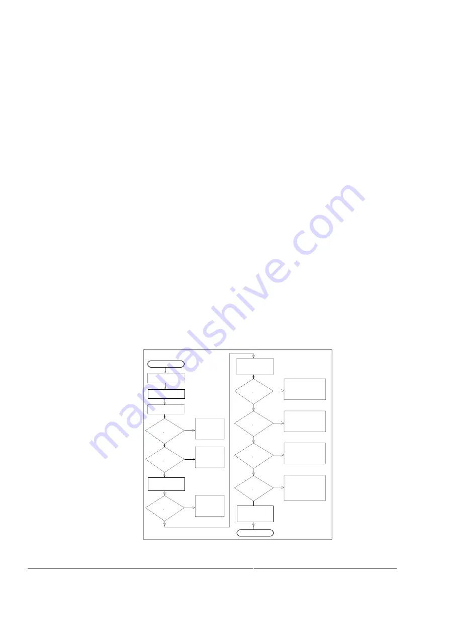
The following sequence will take place when
[ON/OFF] (901)
changes from 0 to 1:
[ON/OFF] (901)
0 --> 1
FAN ON (10908)
0 --> 1
[ACK CONV FAN]
= 1?
No
Yes
FAULT 50:
No converter fan
acknowledge
Excitation contactor
closing command
FIELD ON = 1
[ACK MOTOR FAN]
= 1?
No
FAULT 40:
No external fan
acknowledge
Yes
Yes
Field acknowledge
during 6 sec.
ok?
No
FAULT 39:
No field
acknowledge
Main Contactor
closing command
MAIN CONT ON
= 1
Yes
Main Contactor
acknowledge
= 1
No
FAULT 41:
No main contactor
acknowledge
Net work
phase sequence
ok?
No
FAULT 38:
Phase sequence
fault
Yes
Synchronization
ok?
No
FAULT 31:
Not in synchronism
Yes
Supply voltage
ok?
No
FAULT 29:
Mains undervoltage
or
FAULT 30:
Mains overvoltage
Yes
Output
RDY RUNNING
(10902) = 1
RDY ON (10901)
= 1
NO FAULT
READY FOR RUN
Figure
11
RDY RUNNING sequence.
Содержание DCS 500B
Страница 8: ......
Страница 102: ...Functional Software description 94 DCS 500 Software Description ...
Страница 105: ...DCS 500 Thyristor Power converters Parameter and Signal list Software Version 21 233 Diagram S21V2_0 Appendix A ...
Страница 227: ......


