


XT2640 Operating Manual
13 July 2016
Page 148 of 187
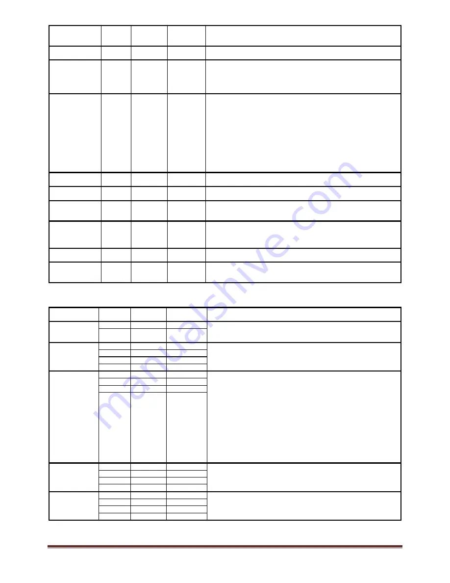
COMMAND
KEYWORD
FIELD(s)
FIELD
FORMAT
FIELD
DATA
RANGE
DESCRIPTION
MTRPOLES
n
NR3
1.0 to 100.0
Sets that the motor has
n
poles, this is used when converting between electrical
drive frequency and motor shaft rotation speed.
MTRSLIP
n
NR1
0 to 3
Sets the motor slip shall be calculated according to
n
as follows‐
0: no motor slip calculation
1: motor slip uses the frequency from VPA1 as the drive frequency
2: motor slip uses the frequency from VPA2 as the drive frequency
3: motor slip uses the frequency from VPA3 as the drive frequency
SPD
n
NR1
0 to 6
Sets that the Motor Speed shall be measured according to
n
as follows‐
0: No speed measurement
1: Speed measured using an analog input on the SPD connector
2: Speed measured using a digital input on the SPD connector
3: Speed measured using a digital input on the SPD connector with direction
indicated by the digital input on the DIR connector
4: Speed derived from the electrical drive frequency measured in VPA1 (only
valid if VPA1 configured for use)
5: Speed derived from the electrical drive frequency measured in VPA2 (only
valid if VPA2 configured for use)
6: Speed derived from the electrical drive frequency measured in VPA3 (only
valid if VPA3 configured for use)
SPDOFFSET
n
NR3
‐1e9 to +1e9
Sets that the offset for speed measurements shall be
n
, in units of rpm. This
only has effect for SPD settings of 1, 2 or 3.
SPDRISING
n
NR1
0 or 1
Sets that the rising edge (
n
=1) or falling edge (
n
=0) of the digital SPD input
shall be detected. This only has effect for SPD settings of 2 or 3.
SPDSCALE
n
NR3
‐1e9 to +1e9
Sets that the scale factor for speed measurements shall be
n
, either in units of
rpm/V (SPD setting 1) or pulses/rev (SPD setting 2 or 3). It has no effect for
other settings of SPD.
TRQ
n
NR1
0 or 2
Sets that the Motor Torque shall be measured according to
n
as follows‐
0: No torque measurement
1: Torque measured using an analog input on the TRQ connector
2: Torque measured using a digital input on the TRQ connector
TRQOFFSET
n
NR3
‐1e9 to +1e9
Sets that the offset for torque measurements shall be
n
in units of Nm. This
only has effect for TRQ settings of 1 or 2.
TRQSCALE
n
NR3
‐1e9 to +1e9
Sets that the scale factor for torque measurements shall be
n
, either in units of
Nm/V (TRQ setting 1) or Nm/Hz (TRQ setting 2). It has no effect for other
settings of TRQ.
24.4.9.7
DATA
LOGGING
CONFIGURATION
COMMANDS
These commands will return an error if used while data logging is running.
COMMAND
KEYWORD
FIELD(s)
FIELD
FORMAT
FIELD
DATA
RANGE
DESCRIPTION
LOGDATA
t
NR1
0 or 1
Sets the data to be saved in each data logging record –
Each record includes a time/date field (
t
=1) or not (
t
=0) and data for each
DDEF field (in order)
0
to
16
fields
DDEF
‐
LOGDELAY
d
NR1
0 to 99
Sets the data logging start delay time to
d
days,
h
hours,
m
minutes plus
s
seconds
h
NR1
0 to 99
m
NR1
0 to 99
s
NR1
0 to 99
LOGFILE
f
NR1
0 or 1
Configures the file used for data logging –
File Format –
f
=0: ASCII
f
=1: Binary
f
=2: Internal (no further fields should be present)
Header –
h
=0: No header (not valid for binary format)
h
=1: Header included
File append –
a
=0: File (if exists) will be overwritten
a
=1: File (if exists) will be appended
File Name (
name
) (excluding extension, first eight characters only) – this is
case insensitive and may only contain valid file name characters for the 8.3
filename format (long file names are not supported).
h
NR1
0 or 1
a
NR1
0 or 1
name
STRING
1 to 8
characters
LOGINTERVAL
h
NR1
0 to 99
Sets the data logging interval time to
h
hours,
m
minutes,
s
seconds plus
f
1/100
th
seconds (if all fields are zero then 0.002s is used)
m
NR1
0 to 99
s
NR1
0 to 99
f
NR1
0 to 99
LOGRUN
d
NR1
0 to 99
Sets the data logging run time to
d
days,
h
hours,
m
minutes plus
s
seconds (if
all fields are 0 then selects manually timed)
h
NR1
0 to 99
m
NR1
0 to 99
s
NR1
0 to 99


