XT2640 Operating Manual
13 July 2016
Page 76 of 187
When the ENT button is pressed the selected time unit area automatically changes to next area to the right, unless the
seconds data is selected when the action is same as pressing the overall RETURN button.
15.2
STARTING
AND
STOPPING
INTEGRATION
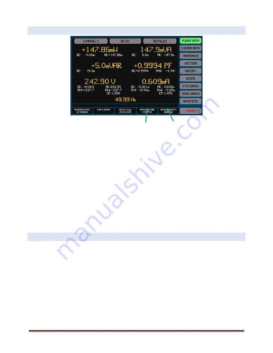
All main screens have an integration info area as shown on the example screen above. This shows the present status of integration
as follows –
STOPPED. Indicates that no integration is presently being performed. To start integration press the Integration Info Area
and press the START button on that screen.
RUNNING. Indicates that a manually controlled integration is being performed. Integration will continue until manually
stopped. Press the Integration Info Area to stop integration.
PAUSED. Indicates that a manually controlled integration is being performed but has been paused by you pressing the
Measurement Info area to hold it. Integration will continue when the measurement hold is released or integration is
manually stopped. Press the Integration Info Area to stop integration.
DELAY. Indicates that a timed integration is being performed and is delaying prior to collecting integrated data. The
progress bar to the right shows how much of the delay has expired. Press the Integration Info Area to stop integration.
RUN. Indicates that a timed integration is being performed and is collecting integrated data. The progress bar to the right
shows how much of the configured run time has expired. Press the Integration Info Area to stop integration.
PAUSE. Indicates that a timed integration is being performed, the delay time has expired, but the XT2640 is not collecting
integrated data because you have held measurement results. The progress bar to the right shows how much of the
configured run time has expired. Press the Integration Info Area to stop integration.
Note:
When starting integration, any previous integration results are always cleared and a new integration is started.
15.3
EXPORTING
OR
RECORDING
INTEGRATED
MEASUREMENTS
The methods for performing this are fully described in section 23.
All measurements can be exported to a .CSV format textual file on an external USB drive attached to the front panel USB port. This
file contains all measurements (including harmonics) for all channels and all VPAs.
Briefly, this is performed by –
Insert the drive into the front panel USB port and wait for it to be READY.
Press the DRIVE INFO area of the screen, the screen shows the file export/import screen.
Press the MEASUREMENTS button. The screen changes to allowing you to enter a file name.
Enter the desired file name (the extension is automatically provided).
If the file already exists then you are prompted to respond if you wish to overwrite it or not.
The file is then written.
Alternatively you can make a record of any measurement screen by saving an image of it to a graphic file on an external USB drive
attached to the front panel USB port.
Briefly, this is performed by –
Insert the drive into the front panel USB port and wait for it to be READY.
Display the screen to be recorded.
Integration
Info Area
Measurement
Info Area


