XT2640 Operating Manual
13 July 2016
Page 72 of 187
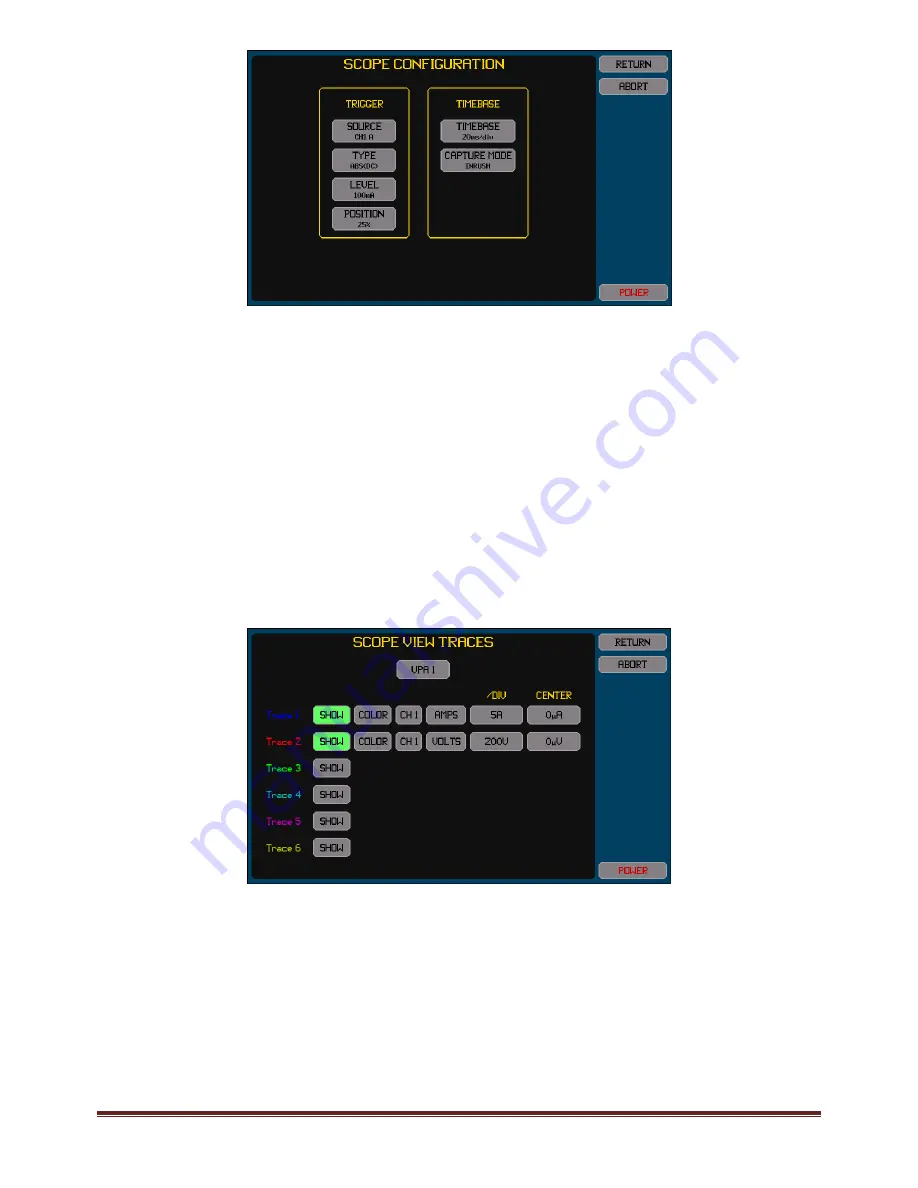
This example uses channel 1 as monitoring the power to the device being tested – any channel configured for
measurements can be used.
This example shows a 100mA trigger level being used. This is a typical trigger level to use for this purpose; however some
devices being tested may draw more than this when turned off, in those cases this level should be increased to above the
current level drawn by the device while turned off (or consider switching the source of the power rather than using the
device power switch).
This example shows 20ms/division as the timebase and the trigger position will be at the 25% position on the screen –
resulting in the final screen having 40ms shown before the trigger event and 120ms afterwards. You can select a different
timebase as required if the inrush event is known to be shorter or longer. The 25% trigger position is recommended for
this type of measurement.
The CAPTURE MODE is selected as INRUSH. This setting tells the XT2640 to automatically ignore any bandwidth limitation
provided by the existing BANDWIDTH setting and also to force the use of the HI range of any unscaled D current option
channels while the inrush capture is in progress. After the capture has been made then these settings will automatically
revert to those configured.
3.
Configure the traces which will be shown on the screen. The screen below shows an example of two traces being configured to
be captured (current and voltage). As shown here, it is useful to include the supply voltage as a trace, as this allows you to
inspect the supply voltage to see if it was being significantly disturbed by the inrush surge current and so having an impact on
the inrush current measurement.
Trace 1 must be the signal which will measure the inrush current; the other traces can be any signals which are also desired to
be captured.
For each trace–
Pressing the SHOW button toggles the trace on/off. The button is highlighted colored green when enabled.
Change the color by pressing the COLOR button until the adjacent trace number shows the desired color.
There are two buttons to the right of the COLOR button which allows you to select the channel and signal to trace. Either
the voltage or current or watts signals may be traced. The watts signal is the result of multiplying the voltage and current
signals. All traces must be in channels configured in the same VPA as that in which the trigger source channel is configured.
The button in the /DIV column allows you to set the scaling in the units of the selected signal. Note that this is entered per
division and there are a total of 6 vertical divisions in the chart (3 above and 3 below the centerline). This can also be set
after the capture has been made to the best 1/2/5 values to show all traces within the extents of the chart when the
AUTOSCALE button is pressed on the SCOPE VIEW screen. This only affects how the trace will subsequently be displayed
and so can be changed afterwards.


