


XT2640 Operating Manual
13 July 2016
Page 151 of 187
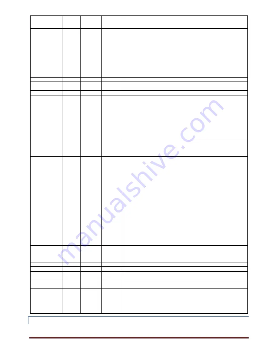
COMMAND
KEYWORD
FIELD(s)
FIELD
FORMAT
FIELD
DATA
RANGE
DESCRIPTION
SPD?
‐
‐
‐
Responds with the NR1 indicating the configured SPD input‐
0: No speed measurement
1: Speed measured using an analog input on the SPD connector
2: Speed measured using a digital input on the SPD connector
3: Speed measured using a digital input on the SPD connector with direction
indicated by the digital input on the DIR connector
4: Speed derived from the electrical drive frequency measured in VPA1 (only valid
if VPA1 configured for use)
5: Speed derived from the electrical drive frequency measured in VPA2 (only valid
if VPA2 configured for use)
6: Speed derived from the electrical drive frequency measured in VPA3 (only valid
if VPA3 configured for use)
SPDOFFSET?
‐
‐
‐
Responds with the NR3 setting for the speed measurement offset
SPDRISING?
‐
‐
‐
Responds with NR1 indicating if the rising edge (1) or the falling edge of the SPD
digital input is being detected
SPDSCALE?
‐
‐
‐
Responds with the NR3 setting for the speed measurement scaling
STBY?
v
VDEF
‐
Responds with the standby power measurement settings for VPA
v
–
If the configured method is EN50564 5.3.2a:
1
st
field is a STRING of value A
2
nd
field is a NR1 with the days minimum measurement time setting
3
rd
field is a NR1 with the days minimum measurement time setting
4
th
field is a NR1 with the days minimum measurement time setting
5
th
field is a NR1 with the days minimum measurement time setting
If the configured method is EN50564 5.3.2d:
1
st
field is a STRING of value D
2
nd
field is a NR3 with the starting power detection level setting
3
rd
field is a NR3 with the ending power detection level setting
TIMEBASE?
‐
‐
‐
Responds with the NR1 scope data capture timebase setting as 5µs (0), 10µs (1),
20µs (2), 50µs (3), 100µs (4), 200µs (5), 500µs (6), 1ms (7), 2ms (8), 5ms (9),
10ms (10), 20ms (11), 50ms (12), 100ms (13), 200ms (14), 500ms (15), 1s (16),
2s (17), 5s (18), 10s (19) or 20s (20)
TRIGGER?
‐
‐
‐
Responds with the scope data capture triggers settings as the following four fields
–
1
st
field (NR1) is the trigger input selection ‐
0: Trigger using CH 1 V input signal
1: Trigger using CH 1 A input signal
2: Trigger using CH 2 V input signal
3: Trigger using CH 2 A input signal
4: Trigger using CH 3 V input signal
5: Trigger using CH 3 A input signal
6: Trigger using CH 4 V input signal
7: Trigger using CH 4 A input signal
2
nd
field (NR1) is the trigger method selection –
0: DC rising edge
1: DC falling edge
2: Rectified signal (rising edge)
3: High Frequency
3
rd
field (NR1) is the trigger position selection ‐
0: trigger is at 0% of the captured time span
1: trigger is at 25% of the captured time span
2: trigger is at 50% of the captured time span
3: trigger is at 75% of the captured time span
4
th
field (NR3) is the configured trigger level in V or A units as applicable
TRQ?
‐
‐
‐
Responds with the NR1 indicating the configured TRQ input‐
0: No torque measurement
1: Torque measured using an analog input on the TRQ connector
2: Torque measured using a digital input on the TRQ connector
TRQOFFSET?
‐
‐
‐
Responds with the NR3 setting for the torque measurement offset
TRQSCALE?
‐
‐
‐
Responds with the NR3 setting for the torque measurement scaling
VSCALE?
c
CDEF
‐
Responds with the NR3 voltage scaling setting (0.0 if not configured for scaling)
for channel
c
VPA?
c
CDEF
‐
Responds with the NR1 indicating which VPA channel
c
is configured in (1 through
3) or if not configured or not installed (0)
WIRING?
v
VDEF
‐
Responds with the NR1 wiring method setting for VPA
v
–
0: N x 1ø method.
1: 2ø3w method.
2: 3ø3w (2 channel) method.
3: 3ø3w (3 channel) method.
4: 3ø4w method
24.4.11
CONFIGURATION
SAVE
AND
LOAD
COMMANDS
These commands allow the user to temporarily save and reload the complete configuration of the XT2640 (the saved configuration is volatile, i.e. it is
not retained after a power cycle).


