XT2640 Operating Manual
13 July 2016
Page 38 of 187
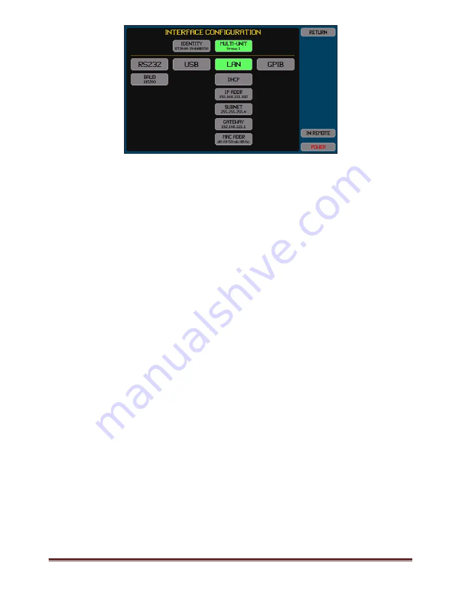
There are two areas shown on this screen. The upper area allows you to set a name (identity) for the XT2640 or to use the factory
default name, and (if option MU is installed) select whether the XT2640 participates in a multi‐unit group and which group number
to participate in.
The lower area allows you to select which interface is to be used to interface to a computer and the configuration to use for that
interface.
The presently selected interface (if any) is shown highlighted in green. Pressing any of the upper interface buttons toggles the
selection active or inactive (only one interface can be active at any time).
Below each interface button are the buttons allowing that interface to be configured, it is not necessary to enable an interface in
order to configure it. Any changes made have an immediate effect.
Note:
The settings for the LAN interface are always used and the LAN interface is always enabled to operate. Whether the LAN
interface is selected (or not) only selects whether the LAN interface can be used to control the XT2640 from a computer.
12.3.2.1
USING
AN
INTERFACE
IDENTITY
The XT2640 can be configured to have a name as an identity associated with this specific instrument as follows –
NONE. This selects that this XT2640 will not have an associated identity and the mDNS protocol will not be used via the
LAN interface.
FACTORY. This selects that this XT2640 will have a name formed from the model number, a dash character and the serial
number. The XT2640 will use the mDNS protocol to establish the uniqueness of this name via the LAN interface.
USER SET. This selects that this XT2640 will have a name which is defined by you. The XT2640 will use the mDNS protocol
to establish the uniqueness of this name via the LAN interface.
12.3.2.2
CONFIGURING
THE
RS232
INTERFACE
For the RS232 interface you must set the baud rate.
12.3.2.3
CONFIGURING
THE
USB
INTERFACE
There are no configuration settings for the USB interface.
12.3.2.4
CONFIGURING
THE
LAN
INTERFACE
12.3.2.4.1
Using
DHCP
to
obtain
the
LAN
Configuration
In this case you press the AUTO‐IP/DHCP/STATIC IP button and select DHCP. There is no other configuration required and if the
LAN interface is enabled the remaining buttons show the configuration obtained (while obtaining the configuration the text in the
buttons is colored orange).
12.3.2.4.2
Using
Manually
set
IP
Information
In this case you press the AUTO‐IP/DHCP/STATIC IP button and select STATIC IP, and then manually enter the IP ADDR, SUBNET
and GATEWAY addresses. You should consult your IT department to obtain the correct settings for these.
If the configured IP address is colored red, then this indicates that the XT2640 has detected another device on the network which is
using that IP address.
12.3.2.4.3
Peer
‐
to
‐
Peer
LAN
Connection
to
a
Computer
In this case you press the AUTO‐IP/DHCP/STATIC IP button and select AUTO‐IP. There is no other configuration required and if the
LAN interface is enabled the remaining buttons show the configuration obtained (while obtaining an IP address in this manner the
text in the buttons is colored orange). This obtains an IP address using the Link‐Local method (defined by RFC3927) and often called
Link‐Local, Zeroconf, IPv4LL, or APIPA. The address selected will be in the range from 169.254.1.0 to 169.254.254.255 and it will
change each time the interface is linked. For a Windows
TM
computer it should be configured for DHCP even if one is not present (in
practice it does not affect operation if one is present as the computer will be able to access the XT2640 at its local address). Since
traffic using this range of IP addresses should not pass through a router, the XT2640 must be local to the computer.
12.3.2.5
CONFIGURING
THE
GPIB
INTERFACE
For the GPIB interface you must set the GPIB address of the XT2640.


