73
12
:
2M
13
:
3M
14
:
4M
15
:
5M
16
:
6M
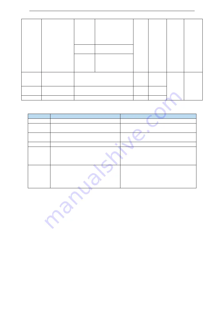
n.x□xx
Stop bit:
0: 2 bits 2: 1 bit
n.□xxx
Parity bit
0: no parity 1: odd
parity
2:
even
parity
P7-02
RS485
communication
protocol
1
:
Modbus
2
:
XNet
2
1
Servo
OFF
At once
P7-05
Slave
station
quantity
1~256
-
10
P7-06
Repeat times
1~500
-
3
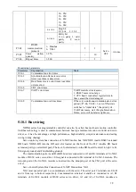
Monitoring parameters
Parameter Explanation
Mark
U0-61
Communication error times
U0-62
Synchronization frame receive error
times (overtime or data error)
U0-64
Data frame receive error times (overtime
or data error)
U0-66
CRC error times
U0-67
UART error times
UART module error reasons:
1. RS485 noise is too large
2. CPU hasn’t read offset register data in
time caused the data damaged.
U0-68
Communication overtime times
If the servo continuous communication error
period ≥P7-06, U0-68 +1, servo XNet state
switches to “initial state”, the priority of
UART decreases, wait the synchronization
frame, servo will not alarm right now.
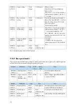
5.10.1 Bus wiring
XD/XG series bus programmable controller can also be called bus multi-axis motion controller.
Fieldbus technology is used to communicate between bus-type multi-axis motion controller and servo
driver, so it has the advantages of high performance, high reliability, simple maintenance and saving
wiring (wiring sharing).
Servo control system bus connection of X-NET motion bus: XDC/XDE inserts RS485 extended
BD board XD-NE-BD into the BD card slot located on the front of the PLC (double BD board
extension port type selects left port). There are four terminals on the BD board, from left to right: A, B,
SG (signal ground) and FG (shielding ground).
The communication ports A and B of BD board are connected to A1 and B1 terminals of JA-NE-L
module of DS3E series servo driver. SG signal is connected to SG terminal of JA-NE-L module. The
nine-pin port of the JA-NE-L module is inserted into the nine-pin port of the CN1 port of the servo
driver.
Servo Control System Bus Connection of X-NET Motion Bus: XG1
XG1 must use serial port 2 to communicate with the servo. The serial port 2 terminals are SG, B
and A from top to bottom respectively. Communication terminal A and B are connected to A1, B1
terminals of JA-NE-L module of DS3E series servo driver, A1 and A2 of JA-NE-L module are


